
EN 50126 – Tutorial (about 60 minutes)
- View
EN 50126 is the European railway standard that sets out how to specify and demonstrate reliability, availability, maintainability and safety – together called RAMS – for a railway system, from the first idea for a project to its final decommissioning. It is used by railway operators and infrastructure managers, by suppliers of trains, signalling and fixed installations, by safety and RAM engineers, and by independent assessors. After this tutorial you will be able to explain what the two parts of EN 50126 ask for, follow its twelve-phase lifecycle, understand how safety requirements and safety integrity levels are derived, and recognise how the standard fits with EN 50129, EN 50716 and the European rules on risk assessment.
Course overview
Edition and status: the current edition is a two-part European Norm prepared by CENELEC technical committee CLC/TC 9X (electrical and electronic applications for railways): EN 50126-1:2017, Railway Applications – The Specification and Demonstration of Reliability, Availability, Maintainability and Safety (RAMS) – Part 1: Generic RAMS Process, and EN 50126-2:2017, Part 2: Systems Approach to Safety. Both carry the year 2017; national adoptions followed from late 2017 (for example, Sweden approved SS-EN 50126-2 in December 2017). They replaced the single-document EN 50126:1999 (later numbered EN 50126-1:1999) together with its corrigenda, and the two CENELEC technical reports CLC/TR 50126-2:2007 and CLC/TR 50126-3:2008. CENELEC confirmed both parts in 2022 after a systematic review. Each part has since been changed by an amendment, EN 50126-1:2017/A1:2024 and EN 50126-2:2017/A1:2024, approved by CENELEC on 14 October 2024 and published from late 2024 into 2025; national adoptions carry dates such as SS-EN 50126-2:2017/A1:2025. For the Part 1 amendment, CENELEC set 30 November 2025 as the latest date for national publication and 30 November 2027 as the date by which conflicting national standards must be withdrawn. Both parts are listed as harmonised standards under the EU railway interoperability directive (EU) 2016/797. The status is therefore current, with amendments; no complete new edition was published as of the verification date. This course teaches the 2017 two-part structure. We did not review the detailed wording of the A1 amendments, so read their forewords before relying on a specific clause. Verified 2026-10-29 against CENELEC catalogue entries (via Genorma), including the 2022 confirmation and harmonised-standard citations, and national standards bodies (SIS, EVS).
Who it is for: engineers, project managers, quality and safety staff, maintenance planners, buyers and auditors who meet EN 50126 on a railway project for the first time – for example because a tender asks for a "RAMS plan", a client demands a hazard log, or an assessor asks how a safety integrity level was derived. It also suits people from automotive, aerospace, medical or industrial automation who already know functional safety and want to understand how rail does it.
Prerequisites: none. A rough idea of how engineering projects move from requirements to design, testing and operation helps. Every railway and RAMS term is explained when it first appears.
By the end of this tutorial:
- You will be able to explain why the railway sector needed a common RAMS standard and what EN 50126 does and does not cover.
- You will be able to define the core vocabulary: reliability, availability, maintainability, safety, hazard, risk, tolerable hazard rate, safety integrity level, hazard log and safety case.
- You will be able to describe the split between Part 1 (generic RAMS process) and Part 2 (systems approach to safety) and name the twelve lifecycle phases.
- You will be able to outline how a project plans RAMS work, analyses risk, applies a risk acceptance principle and turns hazards into requirements for subsystems.
- You will be able to explain how conformity is judged in practice – through verification, validation, independent safety assessment and acceptance – and why there is no "EN 50126 certificate" defined by the standard itself.
- You will be able to place EN 50126 alongside EN 50129, EN 50716, IEC 61508, IEC 62278 and the EU common safety method for risk assessment.
Lesson 1 – Origins, purpose and scope
Why railways needed a RAMS standard
A railway is a large, open, long-lived system. Trains, track, signalling, power supply, stations, staff and passengers all interact, and the equipment bought today may be in service for thirty or forty years. Several organisations share responsibility: the infrastructure manager who owns the track and signals, the railway undertaking that runs trains, the manufacturers who supply rolling stock and equipment, the maintainers, and the national safety authority that grants permission to operate. Each of them cares about two things at once. The railway must be safe, because accidents can kill many people at a time. And it must be dependable, because passengers and freight customers judge a railway by whether trains run on time, and every failure of a door, a point machine or a traction converter can cascade into delays across a network.
Before EN 50126, each country and large operator had its own way of writing requirements for these properties and of accepting new systems. Suppliers selling across Europe faced many processes, and buyers struggled to compare offers because "availability" meant different things in different contracts. CENELEC, the European committee for electrotechnical standardisation, responded with a family of railway standards. EN 50126, first published in 1999, became the top-level one: it gives a shared language for RAMS and a shared lifecycle in which RAMS requirements are specified and then demonstrated.
From one document to two parts
The 1999 edition was a single standard with a fourteen-phase lifecycle. Over the following decade CENELEC added two technical reports to help people apply it: CLC/TR 50126-2:2007, a guide to applying it for safety, and CLC/TR 50126-3:2008, a guide to applying it to rolling stock RAMS. The 2017 revision turned this guidance into normative text, simplified the lifecycle and produced two parts. Part 1 describes the generic RAMS process for all four properties and the lifecycle. Part 2 deepens the safety side: how to define the system being studied, how to analyse and accept risk, how to write and apportion safety requirements, and how to derive safety integrity levels for electronic functions. Part 2 replaced the safety technical report, and Part 1 replaced the 1999 standard and the rolling stock report.
What the standard is for
EN 50126 has three purposes. First, it gives the railway a common understanding of RAMS, so that a client and a supplier mean the same thing when they write "availability of 99.95 %" or "safety integrity level 2". Second, it sets out a systematic, tailorable process – based on a system lifecycle – for specifying RAMS requirements and showing that they have been met. Third, it helps people manage conflicts between the RAMS properties, for example when adding a safety interlock lowers availability, or when a cheaper maintenance regime raises the risk of failures in service.
Scope: what is in and what is out
The standard applies to the three main kinds of railway application: command, control and signalling (interlockings, train protection, train control), rolling stock (trains, trams, metros and their onboard equipment), and fixed installations (power supply, traction substations, overhead lines and similar). It applies at every level, from a complete railway system down to subsystems and components, including software. It applies to new systems, to new systems that are integrated into existing ones, and to modifications of existing systems – but only to the new or modified parts. A system that already exists and is left unmodified does not need to be brought into line retroactively.
Equally important is what EN 50126 leaves out. It does not set numerical RAMS targets for particular applications; the client and the regulator decide those. It does not prescribe technical solutions. It does not define rules for certifying products, and it does not define the process by which a safety authority approves a system. Those topics belong to contracts, to national and European law, and to other standards. Part 2 adds one more limit worth remembering: it does not allow safety integrity levels to be allocated to non-electronic functions, such as a purely mechanical brake component; for those, other forms of evidence are used.
Where EN 50126 comes from conceptually
EN 50126 shares its roots with IEC 61508, the generic international standard for functional safety: both are built around a lifecycle, a risk-based approach and integrity levels. EN 50126 adds reliability, availability and maintainability, reflects the split of responsibilities between railway organisations, and connects to European railway law. Its international counterpart is the IEC 62278 series; check the IEC catalogue for the status of its parts, because the IEC and CENELEC timetables differ.
Lesson 2 – Key concepts and vocabulary
EN 50126 defines a large set of terms. The definitions below are explained in our own words; when you work on a real project, use the definitions in the standard and in the project's glossary, because contracts depend on precise wording.
The four RAMS properties
- Reliability – the ability of an item to perform its required function under stated conditions for a stated period. It is often expressed as a failure rate or as mean time (or mean distance) between failures. A traction motor that fails, on average, once every few hundred thousand kilometres is more reliable than one that fails every few thousand.
- Availability – the ability of an item to be in a state to perform its function when it is needed. Availability depends both on how often things fail and on how long they stay failed, so it combines reliability with maintainability and with the quality of maintenance support.
- Maintainability – the ease and speed with which an item can be kept in, or restored to, a working state when maintenance is done under stated conditions with stated resources. Typical measures are mean time to repair and the time needed for preventive tasks.
- Safety – freedom from unacceptable risk of harm. Safety is not the absence of all risk; it is the condition in which the remaining risk has been judged acceptable using agreed criteria.
- RAMS – the combination of the four properties and, crucially, their interaction. The standard treats RAMS as one of the contributors to the railway's overall quality of service, alongside things like comfort, timetable design and customer information.
Risk vocabulary
- Hazard – a condition or situation that could lead to an accident, such as "train enters an occupied track section" or "passenger door opens on the wrong side". A hazard is not yet an accident; other barriers may still prevent harm.
- Risk – the combination of how often harm is expected to occur and how severe that harm is. Two hazards with the same consequence carry different risks if one is far more frequent.
- Risk acceptance principle – the agreed way of deciding that the risk from a hazard is acceptable. EN 50126-2 recognises three principles that match European law: applying a recognised code of practice, comparing with a similar reference system, and explicit risk estimation.
- Tolerable hazard rate (THR) – the highest rate of occurrence of a hazard (for example, per hour of operation) that is still acceptable once all the other barriers and consequences are considered. A THR is a target set during risk analysis and allocated to the system.
- Tolerable functional failure rate (TFFR) – the highest acceptable rate at which a particular safety-related function may fail in a dangerous way. It is derived from the THR of the hazards that the function's failure can cause.
- Safety integrity level (SIL) – one of four discrete levels (SIL 1 to SIL 4, with SIL 4 the most demanding) that express how much confidence is needed that a safety-related electronic function will perform correctly. The SIL drives the rigour of design, verification and management needed to keep systematic faults out.
- Basic Integrity – the level used for functions whose safety relevance is below SIL 1. It replaced the older label "SIL 0" in the 2017 terminology and still requires sound engineering and quality management.
Process and evidence vocabulary
- System under consideration – the precise boundary of what is being analysed: which equipment, functions, interfaces, people and operating conditions are inside, and what is assumed about everything outside.
- Apportionment – the sharing out of a system-level requirement (for example, an availability target or a THR) among subsystems and components so that, together, they meet it.
- Hazard log – the living record of every identified hazard, its causes and consequences, its risk evaluation, the measures chosen to control it, who owns it and its current status. It is kept up to date for the whole life of the system.
- Safety case – the structured, documented argument, supported by evidence, that a system is acceptably safe for a defined application. EN 50126 calls for it; EN 50129 describes its structure in detail for signalling systems.
- Verification – confirming, phase by phase, that the outputs of a phase correctly fulfil the requirements given as its inputs ("did we build it right?").
- Validation – confirming that the finished system meets the needs of its intended use and its specified requirements ("did we build the right thing?").
- Independent safety assessment – a judgement by a competent person or body, independent of the design team to an agreed degree, that the safety process has been followed and that the evidence supports the safety claims.
- Railway duty holder – a general term for organisations legally responsible for running part of the railway safely, such as infrastructure managers and railway undertakings; suppliers are often called the railway support industry.
How the RAMS properties interact
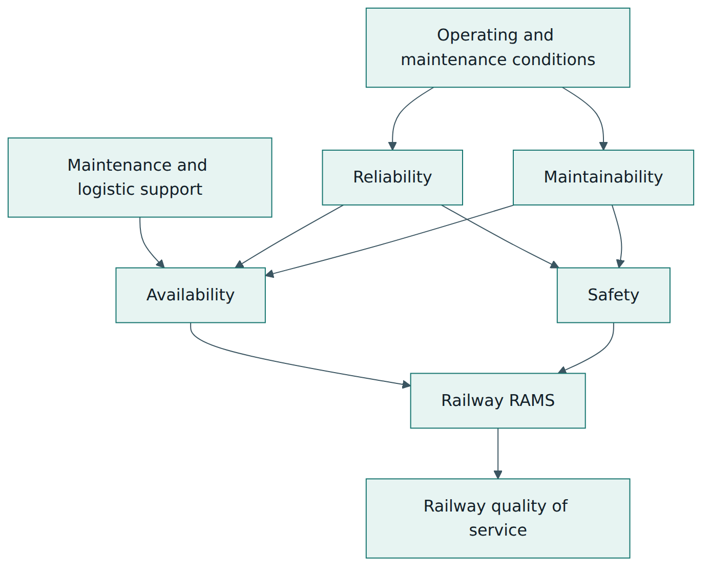
The interaction of the four properties is the heart of the standard. Reliability and maintainability together determine availability. Reliability also affects safety, because many hazards begin with a failure. Maintainability affects safety too: an item that is hard to inspect or repair invites shortcuts. And the way a system is operated and maintained – the environment, the duty cycle, the skill of staff, the spares policy – influences all four. Figure 1 shows these relationships in a simplified form.
Random and systematic failures
Two kinds of failure matter in RAMS work. Random hardware failures happen because physical components wear out or break; they can be predicted statistically from failure-rate data and handled by redundancy, diagnostics and maintenance. Systematic failures come from mistakes in specification, design, software, manufacture or procedures; they recur whenever the same conditions occur and cannot be predicted by statistics. Quantified targets such as THR address random failures, while SILs mainly address systematic failures by demanding disciplined processes and techniques. A good RAMS programme handles both.
Lesson 3 – Structure of the standard
EN 50126 is now two documents that are meant to be read together. This lesson paraphrases how they are organised; it does not reproduce their text.
Part 1 – Generic RAMS process
Part 1 begins, as most European Norms do, with scope, normative references and terms, definitions and abbreviations. It then explains the railway RAMS concepts introduced in Lesson 2: the elements of RAMS, how they relate to quality of service, the factors that influence them (from the system's own design to the operating environment and human factors), and the causes and modes of failure.
Next comes the management of RAMS. Here the standard sets out a risk-based approach, explains that the process must be tailored to the size, complexity, novelty and criticality of the system, and covers organisation, competence, quality management and documentation. It expects RAMS activities to be planned, assigned to named roles and carried out within a quality management system; both parts describe their approach as consistent with the quality management requirements of EN ISO 9001, and they assume that duty holders and suppliers have business-level policies on quality, performance and safety.
The largest section describes the RAMS lifecycle. Since 2017 the lifecycle has twelve phases, and for each phase the standard gives objectives, the inputs needed, the activities to perform for RAM and for safety, and the deliverables that come out. Informative annexes give supporting guidance.
The twelve lifecycle phases
The lifecycle is usually drawn as a "V": the left-hand side moves from a broad idea down to detailed design, the bottom is manufacture, and the right-hand side climbs back up through integration, validation and acceptance into service. Each phase on the right is checked against the corresponding phase on the left.
- Concept – understand the project's purpose, its context and the RAMS implications of the idea, including any existing RAMS performance and constraints.
- System definition and operational context – define the system's mission, boundary, interfaces and the conditions in which it will operate and be maintained; prepare the RAMS planning.
- Risk analysis and evaluation – identify hazards, analyse and evaluate risks, choose risk acceptance principles and open the hazard log.
- Specification of system requirements – state the overall RAMS requirements, including the safety requirements that follow from the risk analysis, together with acceptance criteria.
- Architecture and apportionment of system requirements – design the system architecture and share the system requirements out to subsystems and components.
- Design and implementation – design, build and verify the subsystems and components, producing the evidence that they meet their apportioned requirements.
- Manufacture – produce the equipment under controlled processes so that the as-built product matches the verified design.
- Integration – assemble and install the subsystems into the complete system and check that they work together.
- System validation – show that the integrated system meets its specified RAMS requirements and is fit for its operational context; complete the safety case.
- System acceptance – the client and, where relevant, the authorities accept the system for entry into service on the basis of the evidence and assessments.
- Operation, maintenance and performance monitoring – run and maintain the system, collect RAMS performance data and act on deviations, while controlling modifications.
- Decommissioning – take the system out of service and dispose of it in a controlled, safe way.
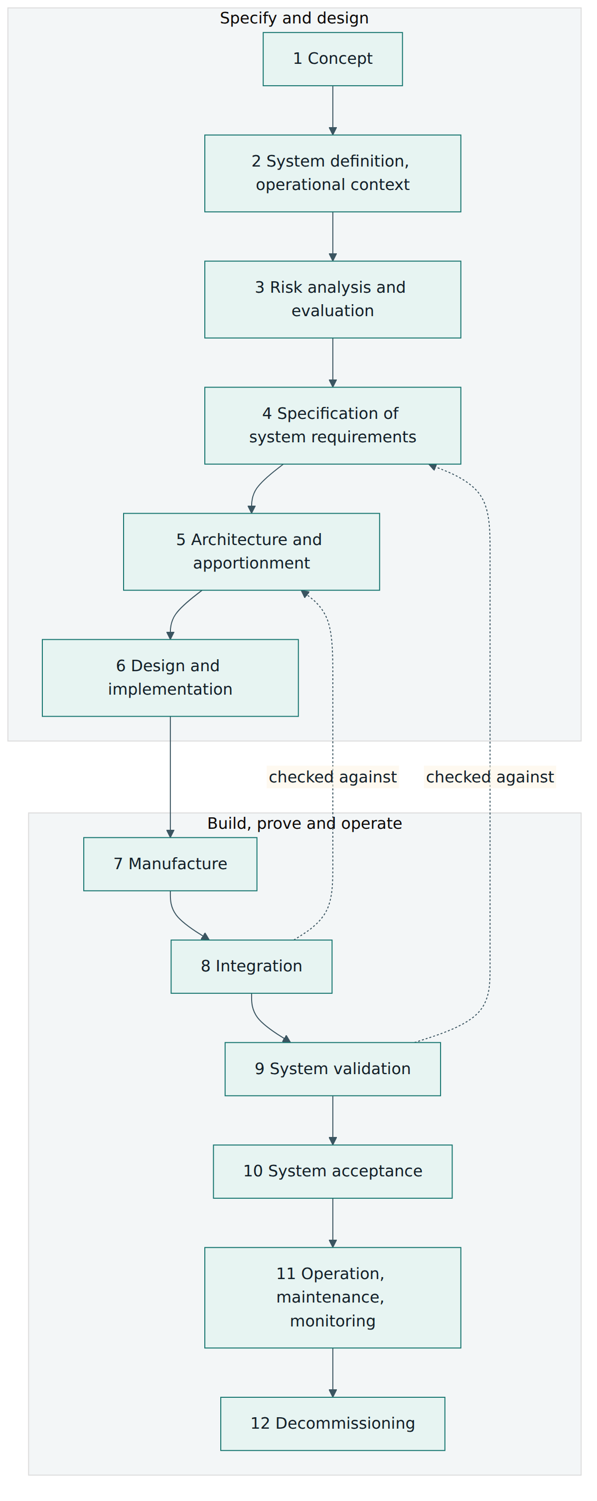
Compared with 1999, the main changes are that "operational context" now appears at system definition, risk analysis is followed by explicit risk evaluation, installation is folded into integration, and the old separate phases for performance monitoring and for modification and retrofit are merged into operation and maintenance. Modifications are handled by re-entering the lifecycle at the appropriate phase for the changed part.
Part 2 – Systems approach to safety
Part 2 is technology-independent and focuses on the safety-related parts of the lifecycle. Its main topics are:
- Defining the system – how to describe the system under consideration, its functions, its interfaces and its environment, at the right level of detail for safety analysis.
- The safety process and safety demonstration – how the safety activities fit the lifecycle, and how safety is argued and accepted through the safety case.
- Organisation and independence of roles – which roles exist in the safety process and how independent the verifier, validator and assessor must be from the designers, depending on the level of risk.
- Risk assessment – hazard identification, risk analysis and evaluation, and the three risk acceptance principles.
- Specification of system safety requirements – turning the outcome of risk assessment into functional safety requirements, safety integrity requirements and other safety requirements.
- Apportionment of functional safety requirements – allocating hazard rates to functions and subsystems, deriving tolerable functional failure rates and from them SILs for electronic functions.
- Design and implementation – what the safety process expects from the design and implementation phase so that the apportioned safety requirements are met and shown to be met.
Lesson 4 – How it works in practice
Tailoring and planning
Nothing in EN 50126 is meant to be applied blindly. Early in the project – in the concept and system definition phases – the parties decide how the lifecycle will be applied: which phases are relevant, who is responsible for each, what documents will be produced and what level of rigour is justified by the risks and the novelty involved. Replacing a station lighting circuit with a like-for-like product needs very little; introducing a new automatic train operation function on a busy metro needs the full process. This tailoring must be documented and justified, because an assessor will later ask why an activity was skipped.
The planning is recorded in plans for RAM and for safety (many projects combine them into one RAMS plan). These describe the organisation and roles, the lifecycle activities and their timing, the analyses to be carried out, the documentation, the verification and validation approach, the interfaces with other parties, and how hazards will be tracked. The plans are living documents: they are reviewed and updated as the project develops.
Roles and responsibilities
EN 50126 recognises that responsibilities are shared. The railway duty holder – an infrastructure manager or railway undertaking – usually owns the operational risk, defines the operational context and sets the top-level targets. The railway support industry – suppliers and integrators – designs and builds systems to meet the apportioned requirements and produces the evidence. A safety authority may grant authorisations under national and European law. An assessor gives an independent judgement. Inside each organisation, typical roles include a project manager, a RAM manager, a safety manager, designers, a verifier and a validator. Part 2 explains that the higher the safety integrity required, the more independence is needed between those who design and those who check.
Risk assessment and risk acceptance
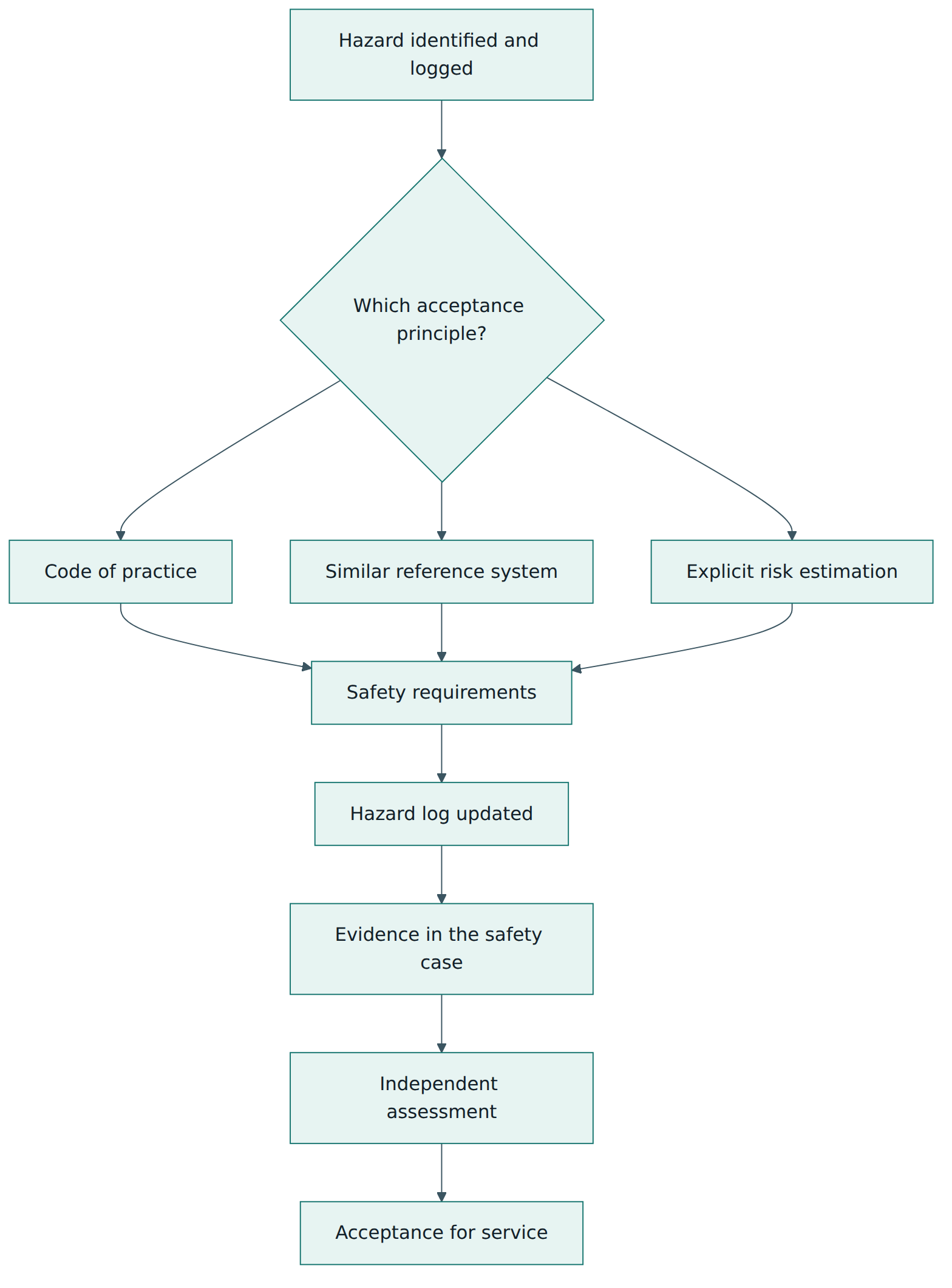
Risk assessment is the engine of the safety process. The team identifies hazards systematically – using workshops, checklists, functional failure analysis, hazard and operability studies, experience from similar systems and accident data – and records them in the hazard log. For each hazard it analyses causes and consequences and then evaluates whether the risk is acceptable. That judgement is made with one of three risk acceptance principles:
- Application of codes of practice – if a widely recognised code, standard or rule set covers the hazard and its use conditions, applying it correctly is accepted as controlling the risk. Example: designing platform edge markings to an established national rule.
- Comparison with a similar reference system – if a system already in service has proven acceptable and the new one is sufficiently similar in function, conditions and use, the new one can be accepted as at least as safe by showing the similarity and handling any differences.
- Explicit risk estimation – when neither of the above fits, the team estimates the risk quantitatively or qualitatively and compares it with explicit acceptance criteria, deriving safety requirements (including THRs) that bring the risk to an acceptable level.
These three principles are the same ones used in the EU common safety method for risk evaluation and assessment (CSM-RA, Commission Implementing Regulation (EU) No 402/2013). That alignment is deliberate: it lets a project use one process to satisfy both the standard and the legal obligation. You will also meet older criteria in railway safety literature – ALARP (as low as reasonably practicable), GAME (globally at least equivalent, a French approach) and MEM (minimum endogenous mortality, a German approach). The 1999 edition described them; today they are mainly background for understanding how explicit acceptance criteria are chosen.
From hazards to safety integrity levels
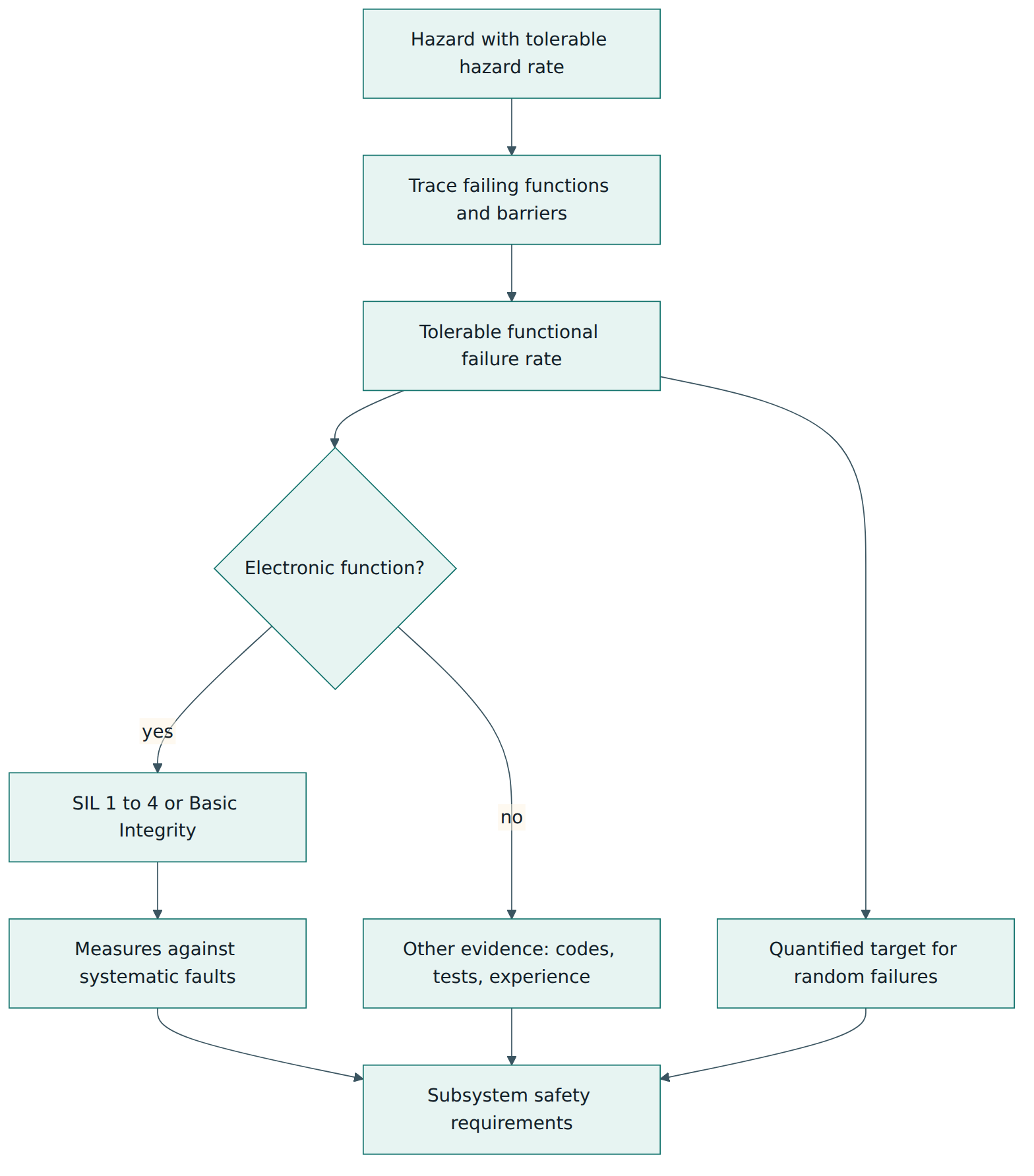
When explicit risk estimation produces a tolerable hazard rate, Part 2 shows how to turn it into requirements for the functions that could cause the hazard. The chain works like this. A hazard at the boundary of the system under consideration receives a THR. The team traces which functions, if they failed dangerously, would lead to that hazard, taking into account any other independent barriers. That gives each function a tolerable functional failure rate. For safety-related electronic functions, the TFFR is mapped onto a SIL using the railway SIL table, published for example as Table A.1 of EN 50129:2018: a TFFR from 10⁻⁹ up to (but not including) 10⁻⁸ per hour corresponds to SIL 4, the next decade (10⁻⁸ to 10⁻⁷ per hour) to SIL 3, then SIL 2 (10⁻⁷ to 10⁻⁶) and SIL 1 (10⁻⁶ to 10⁻⁵). Functions with lower safety relevance receive Basic Integrity. EN 50129 then uses the SIL to set requirements for electronic signalling equipment.
Two points are often misunderstood. First, the SIL is a property of a function and of the equipment that implements it, not of a whole train or a whole project. Second, a SIL does not by itself guarantee a failure rate. It sets the level of process rigour that makes systematic faults acceptably unlikely; random hardware failures still have to be shown quantitatively to meet the TFFR. Very demanding targets beyond the SIL 4 band are not met by "more SIL" but by architecture, such as combining independent functions so that a hazard needs several failures at once.
RAM work in parallel
RAM activities run alongside safety. The client states RAM requirements in the system requirements specification: availability targets, reliability targets for defined failure categories (for example failures that stop a train, failures that delay it, and minor failures), maintainability targets and constraints on maintenance windows and costs. The supplier then apportions them, predicts them with techniques such as reliability block diagrams, failure mode effects and criticality analysis (FMECA), fault tree analysis and maintainability analysis, and refines them as the design matures. Life cycle cost thinking often accompanies RAM work, because a more reliable component may cost more to buy but less to own.
RAM requirements are only meaningful if they are measurable. A good specification states what counts as a failure, what is excluded (vandalism, operator error), how operating time or distance is counted, and how and over what period performance will be demonstrated in service. Many disputes between railway clients and suppliers come from vague RAM clauses rather than from poor equipment.
Typical artefacts
Across the lifecycle a project produces a recognisable set of documents. The names vary, but expect the following:
- system definition and description of the operational context, including interfaces and assumptions;
- RAM and safety plans (or a combined RAMS plan);
- hazard identification and risk analysis reports, and the hazard log;
- system requirements specification with RAMS and safety requirements;
- apportionment documents, RAM predictions and safety analyses (FMECA, fault trees and similar);
- verification reports for each phase and the validation report for the system;
- the safety case, with any conditions on how the system must be used and maintained;
- the independent safety assessment report;
- in operation, data on failures and repairs collected through a failure reporting, analysis and corrective action system (FRACAS) and periodic RAMS performance reviews.
Change and operation
Phase 11 is often the longest. The system may run for decades, and during that time hardware becomes obsolete, software is updated, timetables change and new lines connect to the network. Each modification is assessed for its effect on RAMS and taken back through the relevant lifecycle phases, and the hazard log and safety case are kept current. Performance monitoring closes the loop: if measured reliability falls short of the target, the cause is investigated and corrective action is taken, and if field data reveal a new hazard, it is entered into the hazard log and analysed.
Lesson 5 – Assessment, certification and compliance
No certificate defined by the standard
Unlike management system standards such as ISO 9001, EN 50126 does not define a certification scheme. Its own scope states that rules for product certification and the approval process of safety authorities are outside it. Conformity with EN 50126 is therefore shown through the project's evidence – plans, analyses, hazard log, verification and validation reports, safety case – and judged by people who review that evidence. Some certification bodies offer voluntary certificates or statements of conformity for a supplier's RAMS process or for a generic product, and clients may value them, but these are commercial services, not a requirement written into EN 50126.
Verification, validation and assessment
Three layers of checking build confidence. Verification happens inside each phase: reviews, analyses and tests confirm that the outputs meet the inputs. Validation happens on the integrated system and confirms that it meets its RAMS requirements in its operational context. Independent safety assessment sits above both: a competent assessor, independent of the project to the degree demanded by the risk, examines whether the safety process was suitable and properly followed and whether the evidence supports the claims. The assessor's report is a key input to acceptance. Part 2 sets out the expectations for the organisation and independence of these roles; for the most critical functions the assessor must be independent of the project and is often an external organisation.
Acceptance and the legal framework
Acceptance itself is a decision by the client and, where the law requires it, by an authority. In the European Union several legal roles may be involved alongside the standard:
- an assessment body under the common safety method for risk assessment, which gives an independent opinion on whether the risk management process was correctly applied to a significant change;
- a notified body, which checks conformity with the technical specifications for interoperability (TSIs);
- a designated body, which checks conformity with notified national rules;
- the European Union Agency for Railways or a national safety authority, which issues authorisations such as vehicle authorisations.
Because EN 50126 parts are harmonised standards under the interoperability directive, applying them can support a presumption of conformity with the corresponding essential requirements, as described in each standard's informative annex on its relationship to EU law. Outside Europe, operators and regulators frequently require EN 50126 or IEC 62278 by contract, and an independent safety assessor plays the same central role.
Assessing RAM performance
Reliability, availability and maintainability are rarely "assessed" in the same formal way as safety. Instead, they are demonstrated: by prediction during design, by tests such as maintainability demonstrations (timed repair exercises), and above all by measurement in service over an agreed demonstration period, using agreed failure definitions and statistical rules. Contract clauses often link payments or penalties to these results. EN 50126 provides the process and vocabulary; the actual numbers and demonstration rules come from the contract.
Generic products and cross-acceptance
Suppliers prefer not to repeat the whole safety demonstration for every customer. EN 50129 therefore describes safety cases at three layers – a generic product, a generic application and a specific application – and evidence accepted in one railway can be reused in another (cross-acceptance) once differences in operating context, rules and interfaces have been analysed. Explicit application conditions carry the generic assumptions into each specific installation.
Lesson 6 – Worked example
To tie the concepts together, follow a fictional metro operator, "Riverside Metro", as it installs platform screen doors (glass walls with sliding doors along the platform edge) on an existing line with automatic train control. The numbers below are illustrative only; real projects derive their own from their own risk analysis and contracts.
Phases 1 and 2 – Concept, system definition and operational context
The concept is to stop people falling onto the track, reduce intrusions and allow shorter, more regular dwell times. Riverside Metro, as railway duty holder, appoints a project manager and a safety manager, and recruits an independent safety assessor early. The team writes the system definition: screen doors at twelve stations, door controllers, a platform-level control panel for staff, and an interface to the train control system so that train doors and screen doors open and close together. Outside the boundary but recorded as interfaces: the trains, the signalling, the station power supply and station staff procedures. The operational context covers peak crowding, staff presence on platforms, cleaning at night and the four-hour nightly maintenance window. The RAMS plan sets out tailoring: full process for the door–train interface, simplified process for cosmetic finishes.
Phase 3 – Risk analysis and evaluation
Hazard identification workshops with drivers, platform staff, maintainers and the supplier produce a hazard log. Key hazards include: a passenger trapped between a closed screen door and the train as it departs; a screen door opening when no train is present; a door failing to open, so passengers cannot board or leave during an emergency; and glass breakage. For each hazard the team chooses a risk acceptance principle. Glass strength and door closing forces are covered by established codes of practice for doors and glazing. Fire evacuation through doors is compared with a reference system: identical screen doors already accepted on another line with the same train type. The "trapped passenger at departure" hazard is new for this line, so the team uses explicit risk estimation and agrees a tolerable hazard rate with the assessor's scrutiny of the method.
Phases 4 and 5 – Requirements, architecture and apportionment
The system requirements specification states functional safety requirements (for example, the train may only receive permission to depart when every screen door on the platform is detected closed and locked), RAM targets (availability of door service per station, a limit on door failures that delay trains per million door cycles, and a mean time to restore a door controller within the night window) and maintainability constraints (any door module replaceable by two technicians without special lifting gear).
In the architecture, "doors closed and locked" detection is an electronic safety function. Analysis shows that the hazard can still be prevented by other barriers – the train's own door obstacle detection and the platform staff's visual check – but these are not fully independent in crowded conditions. The team derives a tolerable functional failure rate for the detection function that falls in the band for SIL 2 and allocates SIL 2 to it. Door motor control, which cannot cause the departure hazard on its own, receives Basic Integrity. The availability target is apportioned among door modules, controllers and the interface unit.
Phases 6 to 8 – Design, manufacture and integration
The supplier designs the detection function to its SIL 2 obligations under EN 50129 and EN 50716, carries out a FMECA and a fault tree for the departure hazard, and predicts reliability with a block diagram. Verification reports close each design step. Manufacture follows controlled processes with inspection of every door's locking switches. During integration at a test platform and then at each station, the team checks the interface with train control, including degraded modes: what happens when one door is isolated for maintenance, and how staff confirm that an isolated door is safe.
Phases 9 and 10 – Validation and acceptance
System validation includes tests with trains in service conditions, a maintainability demonstration in which technicians replace door modules against the clock, and a review of every hazard log entry to confirm it is closed or transferred with a clear owner. The supplier delivers a safety case for the screen door system, with application conditions such as "isolated doors must be physically locked and marked". Riverside Metro integrates it into its own safety case for the line. The independent safety assessor reviews the process and evidence and reports no outstanding findings beyond two minor observations. Because the change is significant under the national application of the EU risk assessment rules, an assessment body also issues its report. The operator accepts the system into passenger service station by station.
Phases 11 and 12 – Operation and decommissioning
In service, a FRACAS records every door failure. After six months, data show that one controller type fails twice as often as predicted in tunnels with high humidity. The RAM team investigates, the supplier changes a seal, and the modification goes back through design, verification and a reduced validation, with the hazard log updated to confirm the change has no safety impact. The reliability demonstration period in the contract is extended for the affected stations. Twenty-five years later, the doors will be replaced; the decommissioning plan already notes how to remove the glass panels safely while the line stays open.
Lesson 7 – Relationship to other standards and frameworks
EN 50126 sits at the top of a set of railway standards and alongside European law. Understanding the neighbours helps you know where to look for detailed requirements.
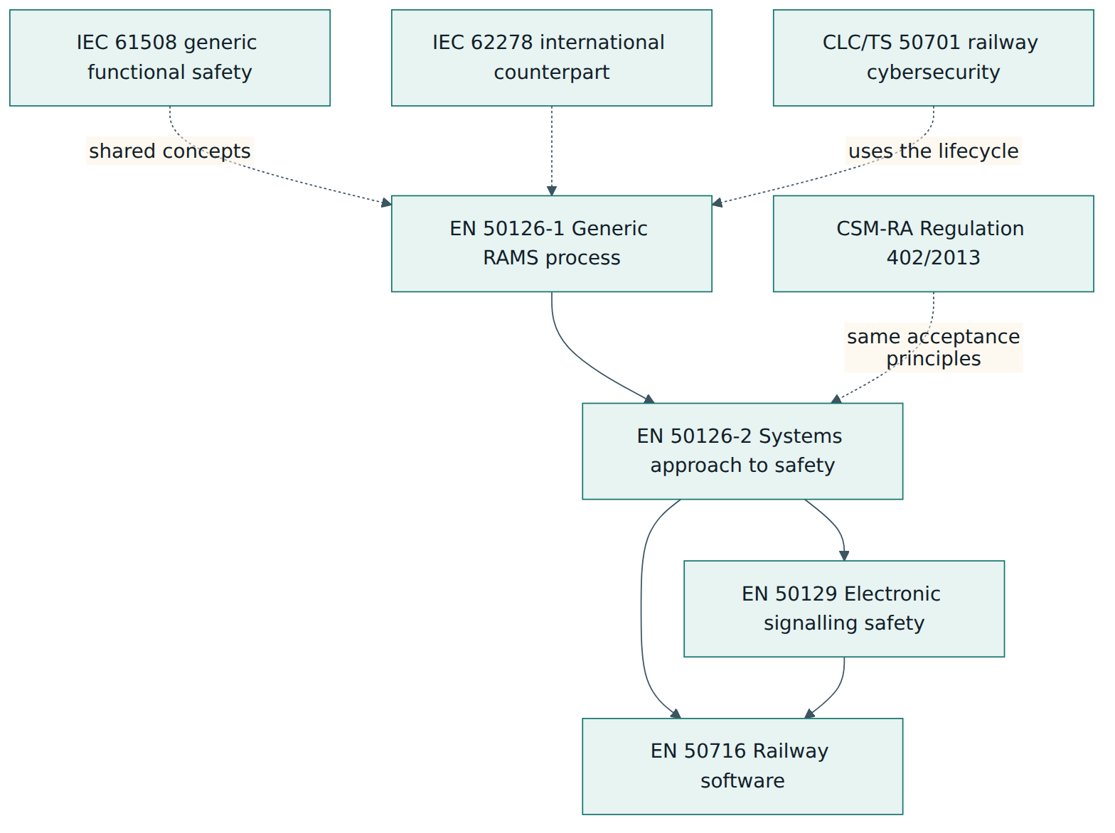
The relationships in Figure 5 can be summarised as follows. EN 50126 decides what RAMS and safety requirements a system needs and how they are apportioned. EN 50129 describes how safety-related electronic systems for signalling demonstrate that they meet their safety requirements, including the structure of the safety case and techniques per SIL. EN 50716:2023 sets the requirements for railway software development; it replaced EN 50128 (signalling software) and EN 50657 (rolling stock onboard software). A further standard, EN 50159, covers safety-related communication over transmission systems. On the security side, CLC/TS 50701 adapts industrial security practice (largely the IEC 62443 series) to railways and organises its activities around the EN 50126 lifecycle so that security and safety work can be coordinated.
| Standard or framework | Main focus | Relationship to EN 50126 |
|---|---|---|
| IEC 61508 | Generic functional safety of electrical, electronic and programmable electronic safety-related systems, any sector | Shares the lifecycle and integrity-level ideas; EN 50126 adapts them to rail and adds reliability, availability and maintainability |
| EN 50129 | Safety-related electronic systems for railway signalling; safety case structure; hardware techniques per SIL | Takes the safety requirements and SILs derived under EN 50126-2 and defines how electronic systems demonstrate them |
| EN 50716 | Railway software development (replacing EN 50128 and EN 50657) | Receives software integrity requirements from the system process and feeds software evidence back into the safety case |
| CSM-RA, Regulation (EU) No 402/2013 | Legal risk management process for significant changes in the EU rail system, with an assessment body | Uses the same three risk acceptance principles; a project can run one process that satisfies both |
| IEC 62278 series | International railway RAMS standard | International counterpart derived from the European text; check its current parts and editions separately |
| CLC/TS 50701 | Cybersecurity for railway applications | Aligns security activities with the EN 50126 lifecycle so security threats to safety and availability are handled together |
| EN ISO 9001 | Quality management systems | Assumed as the organisational foundation on which RAMS activities are carried out |
Common pitfalls and best practices
Common pitfalls
- Starting RAMS work after design. Teams that write the RAMS plan and hazard log only when an assessor asks for them end up reverse-engineering evidence. Risk analysis must shape requirements, not justify a finished design.
- Vague RAM requirements. Targets without failure definitions, exclusions, counting rules and a demonstration method cannot be verified and lead to contract disputes.
- Treating the SIL as a label for the whole system. Assigning "SIL 4" to an entire project wastes effort on low-risk parts and hides which functions actually carry the safety burden.
- A hazard log that stops at acceptance. Hazards closed on paper but never transferred to the operator with owners and conditions become invisible in service.
- Ignoring interfaces. Many hazards arise between subsystems or between organisations; a precise system definition with explicit assumptions about the outside world is essential.
- Using a reference system that is not really similar. Different traffic density, climate or operating rules can invalidate the comparison unless the differences are analysed.
Best practices
- Agree roles and responsibilities between duty holder and suppliers early, including who owns each hazard and each RAM target, and record them in the plans.
- Involve the independent assessor from the planning stage, so that the safety process and the risk acceptance methods are agreed before evidence is produced.
- Make every RAMS requirement measurable and traceable from the hazard log or the client need down to subsystem requirements and back to verification and validation evidence.
- Use the three risk acceptance principles deliberately, choosing codes of practice where they truly apply and reserving explicit risk estimation for novel hazards.
- Design maintainability and support in, because availability depends as much on repair time and spares as on component reliability.
- Collect field data from day one with a FRACAS and review RAMS performance regularly, feeding lessons back into the hazard log and into future designs.
Summary and key takeaways
- EN 50126 is CENELEC's top-level railway standard for specifying and demonstrating reliability, availability, maintainability and safety across the whole system lifecycle.
- The current edition has two parts from 2017 – Part 1 for the generic RAMS process and Part 2 for the systems approach to safety – each changed by an A1 amendment from 2024.
- The four RAMS properties interact: reliability and maintainability create availability, and both influence safety; RAMS contributes to the railway's quality of service.
- The lifecycle has twelve phases, drawn as a V, from concept to decommissioning, and must be tailored and planned for each project.
- Risk is accepted through codes of practice, a similar reference system or explicit risk estimation – the same principles as the EU common safety method for risk assessment.
- Tolerable hazard rates are apportioned to functions as tolerable functional failure rates, and SILs (or Basic Integrity) are assigned only to electronic functions.
- The standard defines no certification scheme; conformity is shown through evidence, verification, validation, independent safety assessment and acceptance.
- EN 50129 and EN 50716 provide the detailed requirements for electronic hardware and software, and the hazard log and safety case keep the RAMS argument alive during operation.
Reflection questions
- Think of a railway or other long-lived system you know. Where would you draw the boundary of the system under consideration, and which interfaces and assumptions would you need to record?
- For a hazard in that system, which of the three risk acceptance principles would you choose, and what evidence would convince an independent assessor that your choice is appropriate?
- How would you write an availability requirement for a fleet of trains so that both the client and the supplier could later agree whether it had been met?
- Which parts of the twelve-phase lifecycle would you tailor down for a small modification, and how would you justify that decision in the plan?
- What information should pass from the supplier's safety case to the operator at handover so that the hazard log and safety case remain valid during decades of operation and change?
Further reading and official sources
- EN 50126-1:2017 Generic RAMS process (catalogue entry with scope, status and replaced documents) – CENELEC, via Genorma
- EN 50126-2:2017 Systems approach to safety (catalogue entry) – CENELEC, via Genorma
- EN 50126-1:2017/A1:2024 amendment (project record) – CENELEC, via Genorma
- SS-EN 50126-2 national adoption with scope and amendment status – SIS / SEK Svensk Elstandard
- CEN and CENELEC – European standardisation organisations – CEN-CENELEC
- Commission Implementing Regulation (EU) No 402/2013 on the common safety method for risk evaluation and assessment – EUR-Lex, European Union
- Common safety methods – European Union Agency for Railways
- Implementing the EN 5012x series – technical white paper – LDRA
Original tutorial by xOps School (DevOpsSchool Private Limited), written from public sources about EN 50126. Not affiliated with or endorsed by the standard's owner; standard names are trademarks of their owners. Buy the official standard from its publisher for the authoritative text.