
EN 50129 – Tutorial (about 60 minutes)
- View
EN 50129 is the European standard that tells railway suppliers, operators and assessors how to show that an electronic signalling system is safe enough to be trusted with people's lives. It covers interlockings, train protection, level crossing controllers, axle counters and similar equipment, and it is best known for one idea: safety is demonstrated through a structured, evidence-based safety case. After this tutorial you will be able to explain what EN 50129 asks for, read its structure, follow how a safety integrity level is derived and met, and understand how a safety case moves from a supplier's generic product to a working railway line.
Course overview
Edition and status: the current edition is EN 50129:2026, Railway applications – Communication, signalling and processing systems – Safety related electronic systems for signalling, prepared by CENELEC, the European committee for electrotechnical standardisation, through its railway committee (CLC/TC 9X). National adoptions appeared during 2026, for example BS EN 50129:2026 (released by BSI in May 2026) and UNE EN 50129:2026 (endorsed in Spain in July 2026). It replaces EN 50129:2018 (corrected in 2019), which itself replaced the first full edition, EN 50129:2003. The previous edition can still be met on running projects until the date of withdrawal given in the foreword of the new edition, so contracts signed under the 2018 text remain common. The international counterpart is IEC 62425:2025 (edition 2), whose scope and layout closely follow the European text. Compared with 2018, the published scope of the 2026 edition explicitly addresses how cybersecurity threats affect functional safety, states that it applies to general-purpose and off-the-shelf equipment to the extent set out in its clause 6.2 (the 2018 scope only said such equipment should be covered where reasonably practicable), and adds a note on systems that are only partly modified. This tutorial teaches the concepts shared by the 2018 and 2026 editions; where a detail (such as a numeric table) is quoted from the 2018 edition, it says so. Verified 2026-10-29 against catalogue entries for BS EN 50129:2026, UNE EN 50129:2026, BS EN 50129:2018 and IEC 62425:2025 and the practitioner sources listed at the end.
Who it is for: systems, hardware and software engineers, safety and RAMS engineers, verification and validation staff, project and bid managers, railway operators and infrastructure managers, and anyone who must write, review or rely on a signalling safety case. It also helps people from other safety sectors (automotive, process, medical) who are moving into rail.
Prerequisites: none. A rough idea of what railway signalling does (keeping trains apart and setting safe routes) is helpful, and the tutorial explains the rest.
Learning objectives. After this course:
- You will be able to explain why EN 50129 exists, what it covers and what it deliberately leaves to other standards and to regulators.
- You will be able to define the core vocabulary: hazard, tolerable hazard rate, tolerable functional failure rate, safety integrity level, basic integrity, safety case and safety-related application condition.
- You will be able to describe the three kinds of evidence a safety case must contain and the conventional parts of a safety case.
- You will be able to trace how a safety integrity level is derived from a hazard and what it means for both random and systematic failures.
- You will be able to distinguish generic product, generic application and specific application safety cases, and explain how conditions flow between them.
- You will be able to describe how independent assessment, safety acceptance and regulatory approval fit together, and why there is no single "EN 50129 certificate" that settles everything.
- You will be able to place EN 50129 next to EN 50126, EN 50716, EN 50159, IEC 61508, IEC 62425 and CLC/TS 50701.
Lesson 1 – Origins, purpose and scope
Why signalling needed its own safety standard
For more than a century, railway signalling relied on mechanical levers and then on electromechanical relays. Signalling engineers developed a strong culture of fail-safe design: a relay was built so that its contacts would drop into the safe position under gravity if power was lost or a coil failed, and a signal would show red if anything went wrong. Safety came largely from the physics of the components, and decades of experience showed which failure modes could and could not happen.
From the 1980s onwards, computers and other programmable electronics began to replace relay interlockings and line-side equipment. Electronics bring huge advantages: more functions in less space, diagnostics, remote control and much cheaper changes. But they do not fail in the friendly, predictable ways a gravity relay does. A microprocessor can produce a wrong output that looks perfectly plausible, a memory cell can flip, and software or hardware design mistakes can sit unnoticed until a rare combination of conditions triggers them. The old reasoning "this component simply cannot fail dangerously" no longer worked on its own.
Railway companies and suppliers therefore needed a common, written way to argue that an electronic signalling system is safe, and a common expectation of how much evidence is enough. Different countries had their own rules, which made it costly to sell a product across borders and hard for authorities to accept work done elsewhere. CENELEC produced a family of railway standards to solve this. EN 50129 is the member of that family that deals with safety-related electronic systems for signalling and with the safety case that demonstrates their safety.
The CENELEC railway family
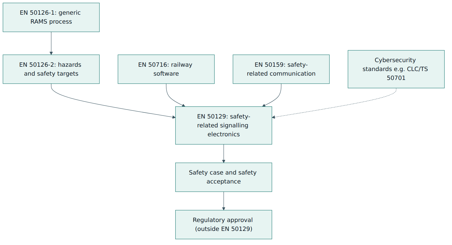
EN 50129 never works alone. It sits inside a group of standards that divide the work between them:
- EN 50126-1 defines the overall RAMS process (reliability, availability, maintainability and safety) and a lifecycle of numbered phases for any railway system.
- EN 50126-2 adds the systems approach to safety: hazard identification, risk analysis, setting safety targets and apportioning them.
- EN 50129 takes those targets for signalling electronics and explains how to design, build, verify, validate and above all demonstrate the safety of the system, its subsystems and equipment.
- EN 50716 (which replaced the older EN 50128 and EN 50657) covers the software inside such systems.
- EN 50159 covers safety-related communication over transmission systems that were not themselves designed for safety, such as radio or shared networks.
What is in scope
According to its published scope, EN 50129 applies to safety-related electronic systems for railway signalling, including their subsystems and pieces of equipment. It applies both to generic systems (a product, or a system that defines a whole class of applications) and to systems built for one specific application. Several boundaries are worth remembering from day one:
- Functional safety only. The standard is about whether the system performs its safety functions correctly and fails safely. Occupational health and safety of staff, sharp edges, electric shock and fire risk from materials are handled by other rules.
- Middle of the lifecycle. It applies across the whole lifecycle but concentrates on the phases of EN 50126-1:2017 from specifying and apportioning system requirements through design, implementation, integration and validation up to phase 10, system acceptance.
- Safety-related systems only. Requirements for functions that have no safety role are outside its scope.
- Purpose-built and off-the-shelf equipment. It is mainly written for equipment designed for signalling, but it also applies, within the limits set in clause 6.2, to general-purpose items such as power supplies and screens bought for use inside a safety-related system. The supplier must show either that such an item is not relied upon for safety or that it can be relied upon for the functions concerned.
- Existing systems. Systems accepted before the relevant date of withdrawal do not have to be re-engineered, but modifications and extensions should follow the current standard as far as reasonably practicable. The 2026 edition notes that a partly modified system may end up with its changed parts meeting the new edition and its untouched parts meeting the old one.
- No approval process. The standard is written for railway duty holders, suppliers, assessors and safety authorities, but it does not define how a safety authority approves anything. That is a matter for law and regulation.
The word "signalling" is meant broadly. In practice EN 50129 is applied to interlockings, train protection and train control (including ETCS and CBTC equipment), radio block centres, axle counters and track circuits, point machines' controllers, level crossing protection, and the computers and networks that tie them together. Other railway domains, such as rolling stock electronics, often borrow its methods even when they follow their own standards.
Lesson 2 – Key concepts and vocabulary
EN 50129 uses a precise vocabulary, much of it shared with EN 50126. The definitions below are paraphrased; always use the standard's own wording in formal documents.
- Hazard – a condition that could lead to an accident, such as two trains being authorised onto the same section of track or a level crossing barrier rising while a train approaches.
- Safety function – a function whose correct operation is needed to keep a hazard under control, for example "prevent a route being set over points that are not detected in the correct position".
- Tolerable hazard rate (THR) – the highest rate at which a hazard may be allowed to occur, usually expressed per hour, set at system level by the risk analysis under EN 50126-2.
- Tolerable functional failure rate (TFFR) – the highest acceptable rate of dangerous failure for one safety function, derived from the THR after taking account of other barriers and of how the function contributes to the hazard.
- Safety integrity level (SIL) – one of four discrete levels (SIL 1 to SIL 4, with SIL 4 the most demanding) that sets the strength of the measures needed to achieve a safety function's TFFR, especially against systematic failures.
- Basic integrity – the label used since the 2017–2018 revision of the family for functions whose safety contribution is below SIL 1; it replaced the older "SIL 0" and still requires sound engineering and quality practice.
- Random hardware failure – a failure that happens at an unpredictable time because a physical component degrades or breaks; its rate can be estimated and reduced by architecture and fault detection.
- Systematic failure – a failure caused by a mistake in specification, design, software, manufacture, installation or maintenance; it will happen every time the triggering conditions arise and cannot be described by a simple failure rate.
- Safety case – the documented, structured argument, backed by evidence, that a system, product or application is adequately safe for its intended use.
- Generic product – a product that can be reused in many applications, such as an interlocking computer platform or an axle counter; its safety case is independent of any particular site.
- Generic application – a configuration or design for a class of applications, such as a standard interlocking design for a type of station layout, built from generic products.
- Specific application – a system for one particular installation, such as the signalling of one named junction, with its own data, layout and site conditions.
- Safety-related application condition (SRAC) – a condition or restriction that must be respected by whoever uses a product or application for its safety claims to remain valid, for example a temperature range, a maintenance interval or a rule for preparing configuration data.
- Fail-safe behaviour – the design property that, when faults occur, the system moves to or stays in a safe state; EN 50129 recognises several ways to achieve it, explained in Lesson 4.
- Hazard log – the living record of identified hazards, their causes, the measures taken and their status, used to manage safety throughout the project.
- Independent safety assessor – a competent person or organisation, independent of the design and project teams to the extent required by the SIL, who judges whether the system and its evidence meet the standard and the safety requirements.
- Safety acceptance and approval – acceptance is the decision by the responsible party that the system is safe enough to be put into use on the basis of the safety case; approval is a separate decision by a safety authority under national or European law.
Random versus systematic: the key distinction
If you understand only one idea from this lesson, make it this one. EN 50129 treats random hardware failures and systematic failures differently because they behave differently. Random failures can be counted and predicted statistically: you can look up or measure failure rates of components, model the architecture and calculate how often a dangerous failure would happen. Systematic failures cannot be counted in the same way; a design error is either present or not. You can only reduce the chance that such errors are present, and limit their effect, by applying disciplined processes, reviews, analysis, testing and independent checks.
That is why a SIL has two faces. For random hardware failures, the design must meet a quantitative target (the TFFR). For systematic failures, the SIL determines which techniques and measures are required, and how strictly, throughout the lifecycle. A design that meets a very low calculated failure rate but was built carelessly does not reach a high SIL.
Lesson 3 – Structure of the standard
EN 50129 is a long document: the British adoption of the 2026 edition runs to about 140 pages. You do not need to memorise it, but you should know where things live. The outline below follows the architecture shared by the current European text and IEC 62425:2025; check the clause numbering against the exact edition named in your contract, because the layout changed significantly between 2003 and 2018.
Main clauses
- Clauses 1 to 4 – scope, normative references, terms and definitions, abbreviations and the general framework.
- Clause 5 – requirements for developing safety-related electronic systems, organised along the lifecycle phases of EN 50126-1 up to the point where the system is ready for acceptance. It covers the organisation and its independence, quality and safety management, and the technical work of each phase.
- Clause 6 – specific topics that cut across the lifecycle: for example the use of pre-existing systems and off-the-shelf equipment (6.2 in the 2026 edition), tools that can affect safety, the impact of cybersecurity threats on functional safety, and particular points about specific application safety cases.
- Clause 7 – the structure and content of the safety case.
- Clause 8 – safety acceptance and approval: what must be in place before the system can be accepted, and how this connects to the separate approval by an authority.
Annexes
- Annex A – how safety integrity requirements are specified and allocated, including the relationship between TFFR and SIL.
- Annex B – detailed technical requirements on the effects of faults, independence of items, detection and negation of faults, and related topics. In the current generation this material is normative.
- Further annexes – tables of techniques and measures to avoid systematic faults and to control random and systematic faults, graded by SIL (normative in the current generation); guidance on component failure modes; and an informative annex on user-programmable integrated circuits such as FPGAs.
Three kinds of evidence
Underneath this layout runs a simple idea that has been part of EN 50129 since its first edition. A system is ready for safety acceptance only when three kinds of evidence are present, and all three appear in the safety case:
- Evidence of quality management – the organisation works under an effective quality management system covering the whole lifecycle, which reduces the chance of human error at every stage.
- Evidence of safety management – a specific safety process has been followed: a safety plan, hazard log, competent and suitably independent people, verification and validation, configuration control and so on.
- Evidence of functional and technical safety – the system itself, as designed and built, performs its safety functions correctly, copes with faults and with its environment, and has been tested to show it.
Quality and safety management mainly address systematic failures. Technical safety addresses both kinds, and is where the analyses of fault effects and the quantitative targets live.
The parts of a safety case
The standard describes a conventional structure for the safety case. In practice it has six parts, and many railways and assessors expect documents to follow this order so they can find things quickly.
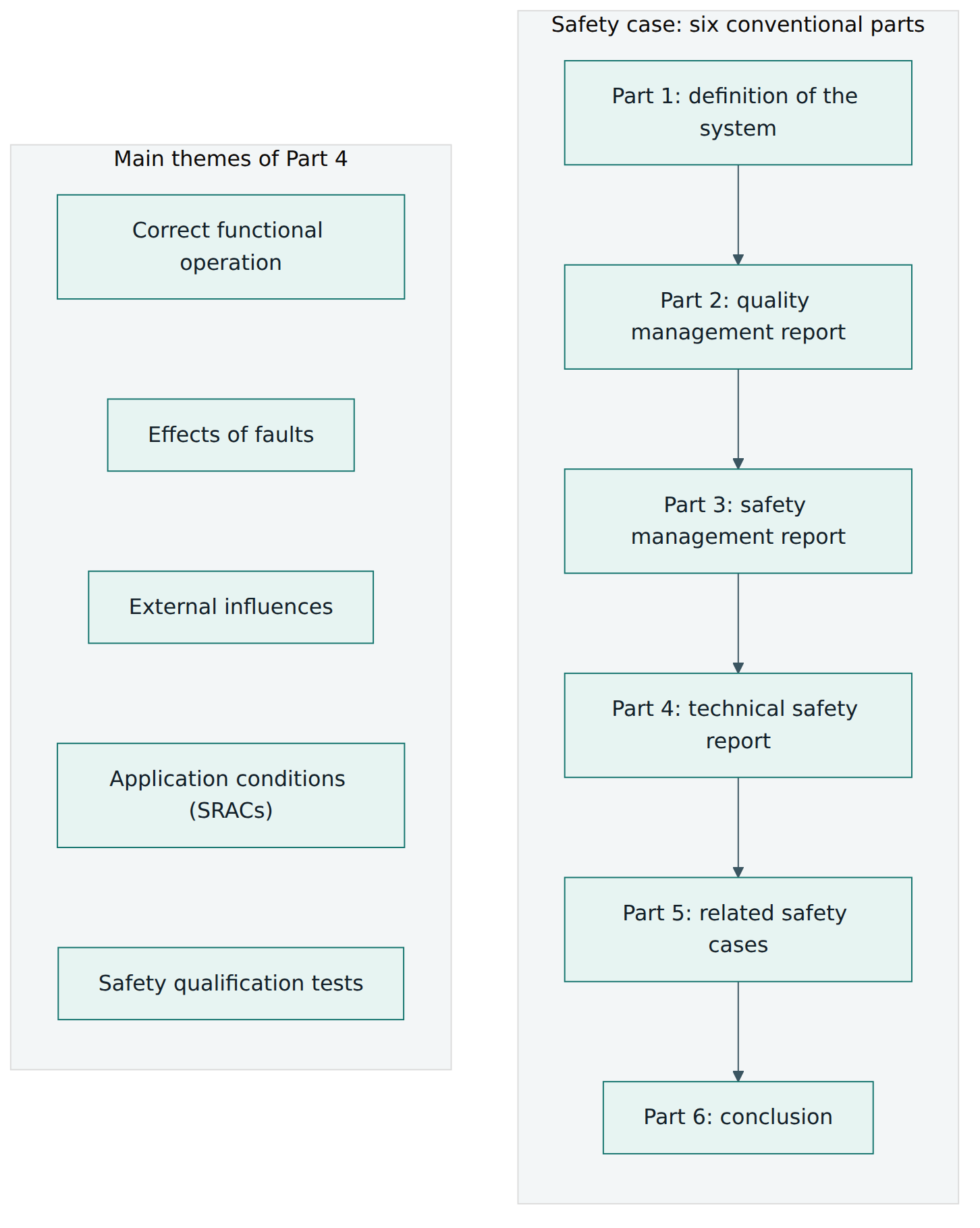
- Definition of the system states exactly what the safety case is about: the product or system, its version and configuration, its boundaries and interfaces, and the documents that define it. A safety case for "the interlocking" without a version is worthless.
- Quality management report gives the evidence that quality management was applied.
- Safety management report gives the evidence that the safety process was applied, including the hazard log, the verification and validation results and the independence arrangements.
- Technical safety report explains why the design is safe: that it works correctly in normal conditions, what happens when components fail, how it withstands its environment (temperature, vibration, electromagnetic interference, power disturbances), which conditions its users must respect, and which tests demonstrated its safety.
- Related safety cases lists the other safety cases this one relies on, such as those for the generic products it uses, and shows that their conditions are met.
- Conclusion summarises the claim, the limits of that claim and the SRACs exported to the next user.
Lesson 4 – How it works in practice
From hazard to SIL
The work starts at system level under EN 50126-2. The railway or system integrator identifies hazards, analyses the risk they create, and decides how often each hazard may be tolerated: its THR. Safety requirements are then apportioned to the parts of the system. EN 50129 picks up this flow for the signalling electronics.
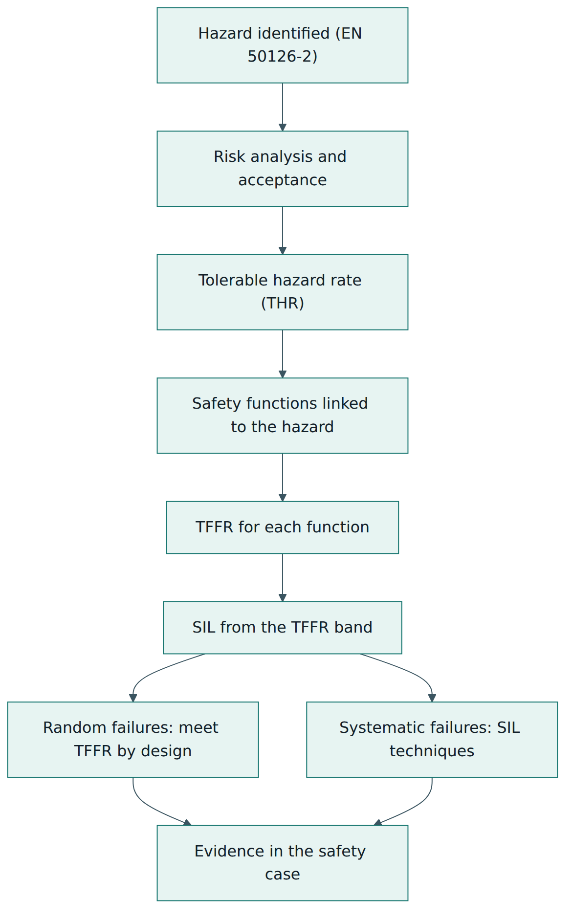
Each hazard is linked to the functions whose dangerous failure could cause it. Using the THR and the logic of how failures combine (for instance whether another independent barrier must also fail), the engineers derive a TFFR for each safety function. The TFFR is then mapped to a SIL using the table in Annex A. In the 2018 edition that table uses decade-wide bands per hour: a TFFR from 10⁻⁹ up to (but not including) 10⁻⁸ per hour corresponds to SIL 4, the next decade up to 10⁻⁷ to SIL 3, then up to 10⁻⁶ to SIL 2 and up to 10⁻⁵ to SIL 1. Check the edition you work to for the exact table and conditions.
Two points often surprise newcomers. First, the SIL belongs to a function, not to a box: a single computer may perform functions of different SILs, and then it must be built to the highest unless the functions are shown to be independent. Second, the SIL is a target to be met, not a label to be claimed. Reaching it requires both a design whose random failure rate is low enough and a lifecycle disciplined enough for the systematic side.
Designing for fail-safety
Because electronics can fail in many ways, the standard expects the design to make dangerous failures either impossible or detected and neutralised in time. Three classic approaches appear in railway practice and in the standard's technical annex:
- Composite fail-safety – each safety-related function is performed by at least two independent items, and a safe output is only produced when they agree. A fault in one item causes disagreement, which is detected and leads to a safe state. The well-known "two-out-of-two" computer architecture works this way.
- Reactive fail-safety – a single item performs the function, but its safe operation is checked so quickly and thoroughly (for example through coded processing or continuous self-tests) that any dangerous fault is detected and its effect negated before it can matter.
- Inherent fail-safety – every credible failure mode of the item is itself non-hazardous, as with traditional gravity-operated safety relays. This is only possible where the physics allows it to be proven.
Whichever approach is used, the technical safety report must show that a single random fault cannot lead to a dangerous failure for the higher SILs, and that faults are detected and negated within a time short enough that a second fault is very unlikely to occur first. This is where independence of items matters: two channels that share a power supply, a clock, a component batch or a software design error are not truly independent, and the analysis must look for such common cause failures. The standard's annex material explains which failure modes of common component types must be assumed and when a failure mode may be excluded with proper justification.
Managing the project
Alongside the design work runs the management side that produces the quality and safety evidence. Typical activities and artefacts include:
- a safety plan describing the lifecycle, organisation, responsibilities, independence, documents and reviews for the project;
- a hazard log opened early and kept up to date until the system leaves service;
- requirements specifications for the system, subsystems and equipment, with safety requirements clearly identified and traceable back to hazards;
- hazard analyses such as failure modes, effects and criticality analysis, fault tree analysis and interface hazard analysis;
- verification at each phase (does the output of this phase correctly reflect its input?) and validation of the finished system (is it fit for its intended use and does it meet the safety requirements?);
- configuration and change management, so that the evidence always matches the exact version delivered;
- competence management, so that each person's training and experience suit their role.
Roles and independence
The standard names roles rather than job titles: a project manager, designers and implementers, verifiers, validators and an assessor, with a safety manager or similar role in practice. The higher the SIL, the stronger the independence it expects between those who create the design and those who check it. At SIL 3 and SIL 4, verification and validation must be organisationally independent of the design team to a defined degree, and the assessor must be independent of the project altogether. At lower levels some roles may be combined. Independence is not a formality: it exists because people find it hard to see their own mistakes, and because commercial pressure on a project manager should not be able to bend a validation verdict.
Generic and specific safety cases
One of EN 50129's most practical ideas is that safety cases are built in layers. A supplier develops a generic product, such as an interlocking platform, and writes a generic product safety case. A system designer then uses one or more products to create a generic application, for example a standard design for a family of stations, with its own safety case that relies on the product cases. Finally the design is adapted to a particular site with its track layout, configuration data and installation: the specific application. Its safety case is often split into one for the application design and one for the physical implementation on site.
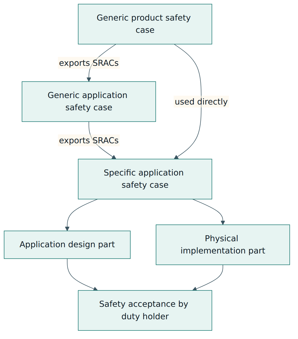
The glue between the layers is the set of SRACs. Every generic case ends with conditions that its users must respect. The next layer up must either satisfy each condition, pass it on to its own users, or show why it does not apply. A condition that is quietly dropped is one of the classic ways safety cases fail, because the generic product's safety claim then no longer holds.
This layering is what makes reuse economical. A product assessed once can be used on many lines; only the application-specific work needs fresh evidence. It also makes clear who is responsible for what: the product supplier for the product, the system designer for the application, the installer and the railway for site work and operation.
Off-the-shelf equipment, tools and cybersecurity
Modern systems use commercial parts and powerful engineering tools. EN 50129 expects the supplier to show that commercial items are either not relied upon for safety or are adequate for what they are relied upon to do. Tools that can introduce errors into the delivered system (such as data preparation tools or compilers) need justification proportionate to their influence. The 2026 edition also asks engineers to consider how deliberate attacks could undermine safety functions, while leaving the detailed security process to the dedicated cybersecurity standards. In practice that means safety and security teams must share their hazard and threat analyses.
Lesson 5 – Assessment, certification and compliance
Independent safety assessment
Assessment is the activity by which an independent, competent assessor forms a judgement on whether the system and the process that produced it meet the requirements, and whether the safety case is credible. The assessor typically reviews plans early, samples evidence during the project, audits processes, witnesses selected tests and finally writes an assessment report. That report, along with the safety case, is a key input to safety acceptance.
Assessment is not the same as verification or validation. Verifiers and validators work inside the project, checking outputs and testing the system. The assessor stands outside and judges the whole, including whether verification and validation were done properly. For SIL 3 and SIL 4 systems the assessor's independence from the supplier's project and commercial interests is essential.
Is there an "EN 50129 certificate"?
Several accredited conformity assessment bodies and independent safety assessors offer certificates or assessment reports stating that a product, at a given version and under stated conditions, conforms to EN 50129 for a given SIL. These are valuable: they let buyers and authorities rely on work already done. But be careful about what such a document means:
- It is not a legal approval to put anything into service. EN 50129 explicitly does not define an approval process.
- It covers only the version, configuration and scope described, and only if its SRACs are met by the user.
- It does not replace the application-specific evidence needed for a particular site.
- It may refer to an older edition; whether that is still acceptable for a new project depends on the contract, the regulator and the transition dates.
So the honest answer is: there is no single, universal EN 50129 certification scheme with a central register. There are independent assessments and certificates from qualified bodies, each with a defined scope, which feed into acceptance and approval decisions.
Safety acceptance and approval
Safety acceptance is the decision by the responsible party, usually the railway duty holder or the system integrator in agreement with it, that the system is safe enough on the basis of the safety case and the assessment. Approval is the separate permission granted by a safety authority. In the European Union, the legal framework includes the railway safety and interoperability directives, technical specifications for interoperability such as the control-command and signalling TSI, and the Common Safety Method for risk evaluation and assessment (Commission Implementing Regulation (EU) No 402/2013). Under that regulation, a proposer managing a significant change engages an independent assessment body, often called an AsBo. Conformity with interoperability specifications is checked by notified bodies. National safety authorities and the European Union Agency for Railways authorise systems and vehicles within their remits.
EN 50129 is widely used as the technical basis for all of these, because it gives a recognised way to structure evidence. A good EN 50129 safety case makes the regulatory steps easier, but it does not perform them. Outside Europe, many railways and metros specify EN 50129 or IEC 62425 in contracts, and the assessor and approver roles are defined by local law or by the customer.
After acceptance
Safety does not end at acceptance. The SRACs become operating and maintenance rules, the hazard log stays open, incidents and defects are analysed, and every modification is assessed for its safety impact. A change to a SIL 4 function, even a small software patch or a data change at one station, needs its own verification, validation and assessment proportionate to its impact, and the safety case must be updated so that it continues to describe what is actually installed.
Lesson 6 – Worked example: a signalling supplier and a regional railway
This example is fictional but realistic. A supplier, "Northline Signalling", develops a new electronic object controller that drives and detects points (the movable rails at a junction) and signals for its computer-based interlocking. A regional infrastructure manager, "Valley Rail", plans to use the interlocking and the new controllers to resignal a busy junction.
Step 1 – Receive the safety targets
Valley Rail's system integrator carried out hazard identification and risk analysis under EN 50126-2 for the resignalling scheme. One hazard is "points move while a train is passing over them"; another is "a signal shows proceed while the points are not detected in the correct position". Each hazard received a THR. The integrator apportioned these to functions, and Northline's controller was given safety functions such as "only command point movement when the interlocking has issued a valid, checked request" and "report point detection only when the detection circuits confirm the correct end position". The resulting TFFRs fall in the SIL 4 band.
Step 2 – Plan the work
Northline writes a safety plan for the controller as a generic product. It defines the lifecycle, appoints a safety manager, separates the verification and validation team from the designers as SIL 4 demands, and engages an independent assessor from a different organisation. The hazard log is opened with the hazards and functions received from the system level, plus product-level hazards discovered later.
Step 3 – Choose a fail-safe architecture
The design team chooses composite fail-safety: two independent processing channels, each built on different hardware batches with separate clocks and power regulation, compute every output. The point motor is only driven when both channels agree and independently energise their parts of the output circuit. The detection inputs are read by both channels and cross-checked. If the channels disagree, the controller removes power from outputs and reports a fault, which the interlocking treats as "points not detected", a safe state that stops routes being set.
The engineers carry out a failure modes, effects and criticality analysis on every component, using the failure modes the standard says must be assumed. They show that no single fault can drive the motor without a valid request, and that any fault is detected within a defined time, which is much shorter than the expected time to a second fault. A fault tree analysis combines component failure rates to show that the dangerous failure rate of each safety function is below its TFFR. A common cause analysis checks shared items, such as the backplane and the input connectors.
Step 4 – Address systematic failures
For the software, the team follows EN 50716 at SIL 4. For the hardware design and the whole product, they apply the techniques and measures the standard recommends at SIL 4: formal reviews of requirements and design, traceability, extensive testing including fault injection, environmental testing for temperature, vibration and electromagnetic compatibility, and careful configuration management. The engineering tool that generates the controller's configuration tables is justified because an error in it could change the safety behaviour.
Step 5 – Write the generic product safety case
The generic product safety case follows the six-part structure. The technical safety report explains correct operation, fault effects, external influences and tests. It ends with a list of SRACs, for example:
- install only in cabinets that keep the temperature within the specified range;
- connect detection circuits only as shown in the approved wiring diagrams;
- prepare configuration data with the approved tool and check it with an independent second process;
- replace the units' backup batteries at the stated interval;
- use the controller only with an interlocking that treats a reported controller fault as "not detected".
The independent assessor reviews the case and the evidence, raises findings, checks the responses and issues an assessment report for the defined version and scope.
Step 6 – Build the application safety cases
Northline's interlocking already has a generic application safety case for "medium junctions". That case is updated to include the new controller: it lists the controller's generic product case as a related safety case and shows how each controller SRAC is satisfied or passed on. For example, the condition about treating a controller fault as "not detected" is satisfied by the interlocking design itself; the battery replacement interval is passed on to the maintainer.
Valley Rail's integrator then prepares the specific application safety case for the junction. The application design part covers the track layout data, route tables and controller configurations prepared for this site, which are verified and validated against the scheme plans. The physical implementation part covers installation, wiring checks, cabinet temperature control, on-site testing and the readiness of operations and maintenance staff.
Step 7 – Acceptance and approval
Valley Rail reviews the specific application safety case, the assessment reports and the hazard log, and accepts the system for service subject to a few operational restrictions recorded as open items. Because the resignalling is a significant change under the European common safety method, an independent assessment body has also been involved and provides its own safety assessment report. The national safety authority's process for placing the infrastructure in service is followed in parallel. The system enters service; the maintainer adds the exported SRACs to its maintenance plans, and the hazard log stays open for the life of the installation.
What the example shows
Each layer did its own job: EN 50126-2 set the targets, EN 50129 governed the product design and the safety cases, EN 50716 governed the software, the assessor provided independent judgement, and law governed approval. The SRACs linked the layers, and the version-controlled safety cases made it clear which evidence covered which equipment.
Lesson 7 – Relationship to other standards and frameworks
EN 50129 is easiest to understand when you see what its neighbours do. The table compares the most important ones.
| Standard or framework | Focus | Relationship to EN 50129 |
|---|---|---|
| EN 50126-1 and EN 50126-2 | RAMS process and systems approach to safety for all railway applications | Provide the lifecycle phases, hazard analysis, THRs and apportionment that EN 50129 starts from; EN 50129 refines them for signalling electronics. |
| EN 50716 (formerly EN 50128 and EN 50657) | Software for railway applications | Defines how software is developed, verified, validated and assessed at the SIL allocated through EN 50129; its evidence feeds the safety case. |
| EN 50159 | Safety-related communication over transmission systems | Adds specific defences (such as message checks and sequence monitoring) when safety data travels over networks; system-level requirements and safety case content stay in EN 50129. |
| IEC 62425:2025 | International counterpart of EN 50129 | Closely mirrors the European text in scope and structure; used in contracts outside Europe. |
| IEC 61508 | Generic functional safety for electrical, electronic and programmable electronic systems | The cross-industry parent of the SIL concept; railway signalling uses EN 50129 as its sector-specific route instead. |
| CLC/TS 50701 and IEC 63452 work | Railway cybersecurity | Handle the security process; EN 50129 considers how security threats can affect safety functions and points to these documents for the security side. |
| Regulation (EU) No 402/2013 (CSM-RA) | Legal risk management process for changes to the EU railway system | Defines the proposer's process and the independent assessment body; EN 50129 evidence is commonly used to satisfy it. |
EN 50129 and IEC 61508
People from process or machinery safety often ask why rail does not just use IEC 61508. Both share the core ideas: risk-based safety targets, safety integrity levels, the split between random and systematic failures, and graded techniques. EN 50129 adapts them to railway realities. Signalling has a long tradition of fail-safe design, very demanding targets for many functions, and a regulatory system built on safety cases and on reuse of products across many lines. The railway family also defines the SIL from a tolerable rate per function rather than using IEC 61508's split between low-demand and high-demand modes.
EN 50129 and software
EN 50129 covers the system, including hardware and the way software is integrated, while EN 50716 covers how the software itself is produced. A SIL 4 safety function implemented partly in software therefore needs both: EN 50129 to show the architecture, fault handling and overall argument, and EN 50716 to show that the software was produced and checked with the rigour SIL 4 requires. The software assessment report becomes one of the pieces of evidence in the system safety case.
EN 50129 and security
Older signalling systems were isolated, and safety analyses assumed that nobody would deliberately attack them. Modern systems use networks, radio and remote maintenance access. A deliberate attack can defeat protections designed only against random faults: for example, a message check that catches transmission noise might be forged by an attacker. That is why the 2026 edition considers cybersecurity's impact on functional safety and why EN 50159 points to security standards for open networks. Safety engineers do not have to become security experts, but they must make sure the two analyses meet.
Common pitfalls and best practices
Common pitfalls
- Treating the SIL as a product label. Teams say "it's a SIL 4 box" without stating which functions, which version, which configuration and which SRACs the claim depends on.
- Dropping application conditions. A generic case's SRACs are not carried into the application safety case or into maintenance instructions, so the generic claim silently stops being valid.
- Relying only on numbers. A fault tree that meets the TFFR is presented as proof of a high SIL, while the systematic side (process, reviews, independence) is weak.
- Weak independence. Channels in a composite design share hidden common causes, or verification and validation staff report to the project manager under schedule pressure.
- Late assessor involvement. The assessor is engaged only at the end, finds fundamental gaps and causes costly rework or delays.
- Stale safety cases. Changes to software, hardware or data are made without updating the safety case, so it no longer describes the installed system.
- Confusing certificates with approval. A product certificate is treated as permission to put a whole site into service.
Best practices
- Start from the hazard log. Link every safety requirement and every SRAC to hazards and keep that traceability alive for the life of the system.
- Plan independence early. Decide the organisation, the assessor and the reporting lines at the start of the project, matched to the highest SIL involved.
- Design for detection. Choose an architecture where faults reveal themselves quickly and lead to a safe state, and analyse common causes explicitly.
- Write SRACs that users can act on. Make each condition specific, testable and addressed to a clear recipient, and track each one to closure.
- Keep the safety case under configuration control. Tie every version of the case to an exact version of hardware, software and data.
- Bring safety and security together. Share hazard and threat analyses so that deliberate attacks on safety functions are considered.
- Check the edition and transition dates. Agree in the contract which edition applies and how existing evidence will be reused when modifying older systems.
Summary and key takeaways
- EN 50129 is the CENELEC standard for safety-related electronic systems for railway signalling; the current edition is EN 50129:2026, replacing the 2018 edition, with IEC 62425:2025 as its international counterpart.
- Its core purpose is to show, through a structured safety case, that a signalling system is adequately safe; it does not itself define regulatory approval.
- Acceptance rests on three kinds of evidence: quality management, safety management, and functional and technical safety.
- Safety targets flow from hazards (THR) to functions (TFFR) to SILs; a SIL demands both a low enough random failure rate and rigorous measures against systematic failures.
- Fail-safe designs rely on composite, reactive or inherent fail-safety, with careful analysis of fault detection, negation and independence.
- Safety cases are layered from generic product to generic application to specific application, linked by safety-related application conditions.
- Independent assessment, safety acceptance by the duty holder and approval by authorities are separate steps that build on one another.
- EN 50129 works with EN 50126, EN 50716, EN 50159 and cybersecurity standards; each covers a distinct part of the safety argument.
Reflection questions
- Think of a safety function in a signalling system you know or can imagine. Which hazard does it protect against, and how would you explain the path from that hazard to the function's SIL?
- A supplier offers you a product with a certificate stating conformity to EN 50129 at SIL 4. What questions would you ask before relying on it for your project?
- For a two-channel composite design, list the possible common causes that could make both channels fail in the same way. How would you detect or design them out?
- Pick three SRACs that a generic product might export. Who in your organisation would need to act on each one, and how would you prove they did?
- Your railway is modifying a system accepted under an older edition of EN 50129. How would you decide which edition applies to the change, and what would you record in the safety case?
Further reading and official sources
- CEN and CENELEC – European standardisation organisations – CEN-CENELEC
- BS EN 50129:2026 catalogue entry with the scope of the current edition – European Standards (BSI adoption)
- IEC 62425:2025, the international counterpart, with its list of technical changes – IEC, via European Standards
- BS EN 50159:2026 Safety-related communication in transmission systems – European Standards (BSI adoption)
- Commission Implementing Regulation (EU) No 402/2013 on the common safety method for risk evaluation and assessment – EUR-Lex
- Common Safety Methods (CSMs) – European Union Agency for Railways
- Implementing EN 5012x – technical white paper (SIL derivation from THR and TFFR) – LDRA
Original tutorial by xOps School (DevOpsSchool Private Limited), written from public sources about EN 50129. Not affiliated with or endorsed by the standard's owner; standard names are trademarks of their owners. Buy the official standard from its publisher for the authoritative text.