
EN 50716 – Tutorial (about 60 minutes)
- View
EN 50716 is the European standard that tells railway suppliers how to develop, deploy and maintain software for signalling systems and for equipment on board trains, with a level of rigour that grows with the risk the software carries. It is used by software engineers, testers, safety and quality managers, independent assessors and the project managers of signalling and rolling stock projects, and it replaces the two older standards EN 50128 and EN 50657. After this tutorial you will be able to explain what the standard covers, how its software integrity levels drive the work, which roles and documents it expects, and how a real project shows conformity.
Course overview
Edition and status: the current and only edition is EN 50716:2023, Railway Applications – Requirements for software development, prepared by CENELEC technical committee CLC/TC 9X (electrical and electronic applications for railways), approved by CENELEC on 30 October 2023 and published in November 2023. It supersedes EN 50128:2011 (with its corrigendum and amendments A1 and A2 of 2020) and EN 50657:2017 (with its 2023 amendment). Its foreword fixes 30 October 2024 as the latest date for national adoption and 30 October 2026 as the latest date by which conflicting national standards must be withdrawn, so the transition period during which the old standards may still be applied ends on 30 October 2026. A draft amendment, EN 50716:2023/prA1, which adds informative guidance on artificial intelligence and machine learning without new technical requirements, went through CENELEC enquiry in 2026; it is a draft, not a published amendment, so this course teaches the 2023 text and mentions the draft only for orientation. Verified 2026-10-29 against the foreword and contents of the published standard (national adoptions I.S. EN 50716:2023, NSAI preview, and ÖVE EN 50716:2024, OVE preview), the iTeh catalogue entries for the standard and the draft amendment, and practitioner commentary.
Who it is for: software developers, testers, verification and validation engineers, quality and safety managers, project managers and buyers who work on railway signalling, train control or on-board rolling stock systems and are new to EN 50716. It is also useful for people who know EN 50128 or EN 50657 and need to understand what changed, and for engineers from other safety sectors (automotive, aerospace, industrial automation) who are moving into rail.
Prerequisites: none. A basic idea of how software is specified, written and tested helps. Every railway and safety term is explained the first time it appears.
By the end of this tutorial:
- You will be able to explain why railway software needs its own standard, what EN 50716 covers and what it deliberately leaves to other standards.
- You will be able to define the core vocabulary: software integrity level, Basic Integrity, verification, validation, assessment, support tool classes, pre-existing software and application data.
- You will be able to describe the structure of EN 50716, from its organisational clauses to its normative technique tables in Annex A.
- You will be able to walk through the software lifecycle the standard expects, including iterative development and the documents each phase produces.
- You will be able to explain how independence of roles, assessment and the system safety case work together to show that software is fit for service.
- You will be able to apply the standard to a realistic signalling product and plan its roles, tools, documents and evidence.
- You will be able to place EN 50716 next to EN 50126, EN 50129, IEC 62279, IEC 61508 and the railway cybersecurity specification CLC/TS 50701.
Lesson 1 – Origins, purpose and scope
Why railway software needs a standard of its own
Modern railways depend on software for functions where a mistake can kill. An interlocking decides whether a set of points may move and whether a signal may show a proceed aspect. Train protection equipment on board supervises the speed of the train and brakes it if the driver does not react. Door controllers decide when it is safe to release the doors at a platform. In each case, a wrong output at the wrong moment can lead to a collision, a derailment or a passenger falling between train and platform.
Hardware fails randomly: a relay contact wears out, a capacitor dries up. Engineers can estimate those failure rates and design redundancy around them. Software is different. It does not wear out; it fails because of systematic faults – mistakes made in the requirements, the design, the code or the tools – that are present in every copy from the day it is installed and wait for the right combination of inputs to show themselves. You cannot measure a reliable failure rate for such faults by testing alone, because no feasible amount of testing exercises every situation. The only practical defence is a disciplined development process: clear requirements, careful design, appropriate techniques, thorough verification and independent checking, all scaled to how much damage the software could cause.
EN 50716 is that disciplined process for railway software. Its introduction makes the honest point that neither quality assurance nor fault-tolerant design can prove a complex program free of faults; what the standard does is define the methods that give enough confidence for a given level of risk.
From two standards to one
For more than a decade, railway software in Europe was governed by two closely related documents. EN 50128, first published in 2001 and revised in 2011, covered software for communication, signalling and processing systems – the trackside world of interlockings and train control. EN 50657, published in 2017, was derived from EN 50128 and covered software on board rolling stock, such as traction control, brake control and door systems. The two texts were largely parallel but differed in details, which created extra work for suppliers who build both trackside and on-board products and for assessors who had to keep two sets of rules in mind.
CENELEC merged them into EN 50716, published in November 2023. The new standard keeps the clause numbering of the old ones wherever it reasonably can – some subclauses are explicitly "intentionally left blank" so that a reference like "7.3.4" still points to the same topic – which makes it easier for organisations to move their procedures and templates across. It also brings the vocabulary into line with the 2017 editions of the railway RAMS standards EN 50126-1 and EN 50126-2, simplifies the clause on organisation, generalises the requirements on programming languages, and adds informative guidance on iterative lifecycles and model-based development.
What the standard covers
In plain words, EN 50716 applies to the development of software for programmable electronic systems used in two areas: command, control and signalling applications, and applications on board rolling stock. It covers all kinds of software in such systems – application programs (including special-purpose languages such as ladder logic for programmable logic controllers), operating systems, firmware and the support tools used to build and check them. It also covers how to reuse software that already exists and how to handle generic software that is configured by data for each installation.
Several boundaries are worth remembering:
- It is about software and the interaction between software and the system it runs in. The system-level safety process is defined elsewhere, mainly in EN 50126 and EN 50129.
- Fixed installations for electric traction power supply, and ordinary power supply such as station offices and shops, are outside its scope; they follow energy-sector or other standards (for traction power, EN 50562).
- Logic designed into programmable chips such as FPGAs is not treated as software here; the standard points to EN 50129 for safety-related use and to EN 50155 for non-safety-related use. Software that runs on a processor built inside such a chip, however, is in scope.
- It is not retrospective. It applies mainly to new developments; an existing system falls fully under it only after a major modification, while minor changes follow its maintenance subclause. Applying it during upgrades of older software is still recommended.
- It does not specify cybersecurity measures. It acknowledges that attacks can affect safety and asks projects to apply dedicated security standards alongside it.
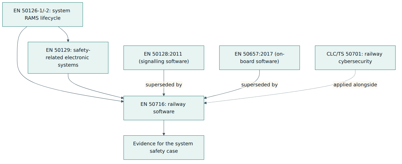
Figure 1 shows the chain of responsibility. The system process in EN 50126 identifies hazards and decides how much risk reduction each function needs; EN 50129 explains how safety-related electronic systems, especially in signalling, demonstrate safety through a safety case; EN 50716 then defines how the software part of those systems must be built so that its contribution to that safety argument is trustworthy.
Lesson 2 – Key concepts and vocabulary
EN 50716 uses a compact vocabulary. Many terms look familiar from general software engineering but carry a precise meaning in this standard. The definitions below are paraphrased explanations, not the standard's wording.
- Software integrity level – a classification that expresses how much confidence is needed that a piece of software is free of dangerous systematic faults. The standard has five levels: Basic Integrity and SIL 1 to SIL 4, with SIL 4 the most demanding.
- Safety integrity level (SIL) – one of the four numbered levels used for safety-related functions. A SIL is allocated at system level according to the risk; the software that implements the function inherits a corresponding software integrity level.
- Basic Integrity – the lowest level, which replaced the old idea of "SIL 0". It applies to software whose failure has only limited safety relevance or none at all; good quality management is required, but the full set of safety techniques and the independent assessment are not.
- Systematic fault – a fault built into the software by a human or tool mistake in specification, design, coding or configuration. It is reproducible: the same conditions trigger it every time.
- Verification – checking, phase by phase, that the output of an activity meets the requirements given to it as input. Answers the question "did we build it the way we said we would?"
- Validation – demonstrating that the finished software meets its specified requirements and is fit for its intended use in the target environment. Answers the question "did we build the right thing?"
- Assessment – an independent evaluation of whether the software, its lifecycle and its evidence conform to the standard and are suitable for the intended purpose. It is required for SIL 1 to SIL 4.
- Independence – a separation between the people who create a work product and the people who check it, so that a reviewer is not under pressure to accept their own work or their manager's schedule. The required degree grows with the integrity level.
- Support tool – any software tool used during development, verification or production of the software, such as an editor, compiler, code generator, static analyser or test harness. Tools are grouped into classes T1, T2 and T3 according to how they can affect the final executable.
- Pre-existing software – software that was not developed specifically for the current project, for example a commercial real-time operating system, an open-source library or a component from an earlier product. It can be used if specific conditions on evidence and suitability are met.
- Generic software and application data – many railway products are built as a generic program that is reused across installations, with each site described by data (track layout, signal names, timings, speed profiles). The standard treats the preparation of that data as a controlled process in its own right.
- Software Quality Assurance Plan (SQAP) – the plan that describes how quality will be achieved on the project: lifecycle, activities, documents, techniques chosen, reviews and responsibilities.
- Traceability – the ability to follow each requirement forward into design, code and tests, and each piece of code back to the requirement that justifies it. It is the backbone of verification.
- Technique and measure tables – the normative tables in Annex A that list development and checking techniques and show, for each integrity level, how strongly each one is recommended.
How strongly is a technique recommended?
The Annex A tables use a small set of ratings that every EN 50716 practitioner needs to read fluently. M means mandatory: the technique must be used. HR means highly recommended: if it is not used, the reason must be explained and justified in the plan. R means recommended: a lesser recommendation that can be adopted as part of a sensible combination. A dash means the standard makes no recommendation for or against. NR means not recommended: if it is used anyway, a justification is needed. Several tables also group alternative techniques and require that an approved combination is chosen, so the standard leaves engineering choice while still setting a floor.
Two simplifications help when reading the tables. First, the techniques required for SIL 1 are the same as for SIL 2, and those for SIL 3 are the same as for SIL 4, so in practice there are three columns of rigour: Basic Integrity, SIL 1–2 and SIL 3–4. Second, the standard does not decide which integrity level a function needs. That decision is made during system risk analysis under EN 50126 and depends on the hazard, on other protective systems and on accepted risk criteria.
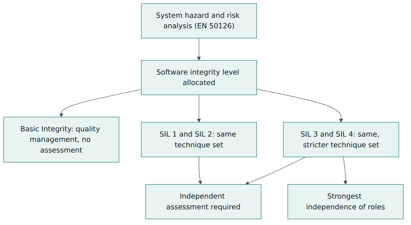
Figure 2 summarises the logic of the whole standard. If you know the software integrity level, you know which column of Annex A to read, how independent your checkers must be, and whether an assessor must examine the work.
Lesson 3 – Structure of the standard
EN 50716 is a substantial document of well over a hundred pages. Its clauses follow the order of EN 50128 so that people who know the older standard can find their way. Here is a paraphrased map of what each part does.
Clauses 1 to 4 – framing
- Clause 1, Scope – the applications and kinds of software covered, the exclusions and the non-retrospective rule described in Lesson 1.
- Clause 2, Normative references – deliberately empty: no other document is required to apply this one, although the foreword says it is read together with EN 50126-1 and EN 50126-2.
- Clause 3, Terms, definitions and abbreviations – aligned with the RAMS standards; the old "integrator" abbreviation is gone because that role no longer exists.
- Clause 4, Software integrity levels conformance – how conformity is claimed, how techniques are selected from Annex A, and what is expected even for software of Basic Integrity, including guidance on mixing components of different integrity levels in one system.
Clause 5 – management and organisation
Clause 5 covers the people side. Subclause 5.1 sets out the organisation and the independence between roles; 5.2 deals with competence, including documented evidence that each person is qualified for their role; 5.3 covers lifecycle issues and documentation, requiring that a lifecycle is chosen, planned and documented, with Annex A Table A.1 listing the typical documents per integrity level. This clause was rewritten for readability in EN 50716 while keeping the organisational options broadly as before.
Clause 6 – software assurance
Clause 6 groups the activities that run across the whole lifecycle rather than belonging to one phase:
- 6.1 software testing, 6.2 software verification, 6.3 software validation and 6.4 software assessment;
- 6.5 software quality assurance, including configuration management and the conditions for pre-existing software;
- 6.6 modification and change control;
- 6.7 support tools and languages, including the tool classes and the qualification evidence each class needs.
Clause 7 – software development
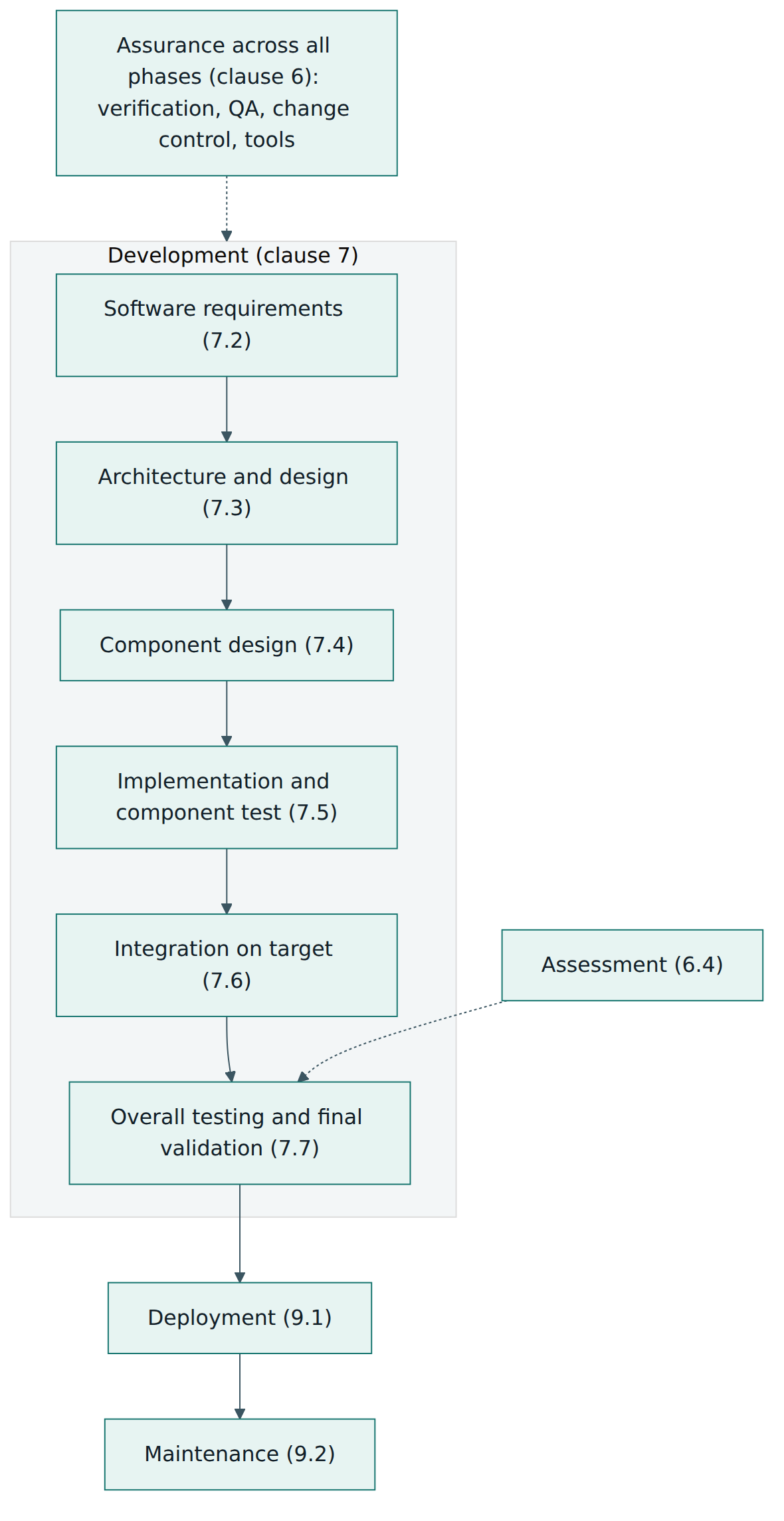
Clause 7 follows the development flow: 7.1 lifecycle and documentation, 7.2 software requirements, 7.3 architecture and design, 7.4 component design, 7.5 component implementation and testing, 7.6 integration, and 7.7 overall software testing and final validation. Each subclause has the same shape – objectives, input documents, output documents and requirements – which makes it easy to build checklists from it.
Clauses 8 and 9 – data, deployment and maintenance
Clause 8 deals with systems configured by application data. It describes an application development process with its own requirements, design, data production, integration and testing, validation and assessment, and controls on the tools and procedures that prepare the data. Clause 9 covers software deployment (getting the right release safely into service) and software maintenance (changing it safely afterwards).
The annexes
- Annex A (normative) – the technique tables, organised by lifecycle activity (lifecycle and documentation, requirements, architecture, design and implementation, component and integration testing, overall testing, quality assurance, maintenance, data preparation) and by detailed topic (coding standards, dynamic analysis and testing, programming languages, modelling, performance testing, static analysis, components and code coverage).
- Annex B (normative) – role specifications for nine key roles: requirements manager, designer, implementer, tester, verifier, validator, assessor, project manager and configuration manager.
- Annex C (informative) – guidance on lifecycle models (linear such as waterfall and V, and several iterative models), on modelling, and on artificial intelligence.
- Annex D (informative) – a bibliography of techniques that briefly describes each technique named in the Annex A tables.
- Annex ZZ (informative) – how the standard relates to the essential requirements of the EU Railway Interoperability Directive (EU) 2016/797 and the technical specifications for interoperability (TSIs) for control-command and signalling and for rolling stock.
What changed compared with EN 50128 and EN 50657
The foreword lists the significant technical changes, which can be summarised as: better alignment with EN 50126-1 and EN 50126-2; a rewritten organisation clause; Annex A realigned to the lifecycle phases; new guidance on lifecycle models and on modelling in Annex C; more guidance for systems that combine software components of different integrity levels; and programming-language requirements expressed as general criteria instead of named languages. Practitioner commentary adds detail: the integrator role has been dropped, with integration work shared by implementer and tester; Basic Integrity replaces SIL 0; and the language table now describes desirable properties – such as strong typing, support for modular programming and testability – so that newer languages can be evaluated on their merits.
Lesson 4 – How it works in practice
Planning: choosing a lifecycle and writing it down
EN 50716 does not impose a particular lifecycle. It requires that the project chooses one, documents it and shows how every required activity and document fits into it. Annex C illustrates linear models (waterfall and the V model) and several iterative models, in which the software is built and verified in increments. This is an important change in tone from the older standards, which were usually read as V-model only. Agile-style iterations are acceptable as long as each increment still produces the required evidence and the final release is verified, validated and assessed as a whole.
The plan that captures these choices is the Software Quality Assurance Plan, normally supported by a configuration management plan, a verification plan and a validation plan. Together they say who does what, which techniques from Annex A will be used and why, how documents are reviewed and approved, and how changes are controlled.
The phases and their outputs
Figure 3 shows the flow. In each phase, people produce work products, a verifier checks them against their inputs, and the results are recorded so that an assessor can later reconstruct what happened.
- Software requirements. System requirements allocated to software, including the safety requirements and the integrity level, are turned into a Software Requirements Specification. In parallel, the team writes the overall software test specification, so that every requirement has a planned way to be demonstrated. Requirements must be unambiguous, testable and traceable to their system source.
- Architecture and design. The architecture defines the major software parts, their interfaces, how they protect each other, and how pre-existing software and generic software fit in. This is where safety strategies such as defensive programming, error detection, diverse checking or partitioning of components of different integrity are chosen. The programming language and coding standard are selected here, using the criteria in Table A.15 and the coding-standard expectations in Table A.12.
- Component design. Each component receives a design specification and a test specification. For Basic Integrity the component design and component test documents are not required at all, and the architecture and design specifications are only recommended, which is one way the standard scales effort.
- Implementation and component testing. Code is written to the coding standard, checked by static analysis and reviews, and tested at component level. At higher levels, structural code coverage targets (Table A.21) show how thoroughly tests exercised the code.
- Integration. Components are combined and tested together, first in simulation and then on the target hardware, according to an integration test specification written by the tester.
- Overall software testing and final validation. The complete software is tested against its requirements in a representative environment, and the validator decides whether it is fit for its intended use, recording the decision in the validation report.
- Deployment and maintenance. The release is installed in a controlled way with release notes that identify exactly what is delivered and under which constraints. Later changes go through impact analysis, re-verification and, where needed, re-assessment.
Roles and independence
The people side is just as important as the document side. Annex B describes nine roles with their responsibilities and the competence each one needs. The core idea is simple: the people who check must not be under the control of the people whose work they check, and the stronger the integrity requirement, the stronger the separation.
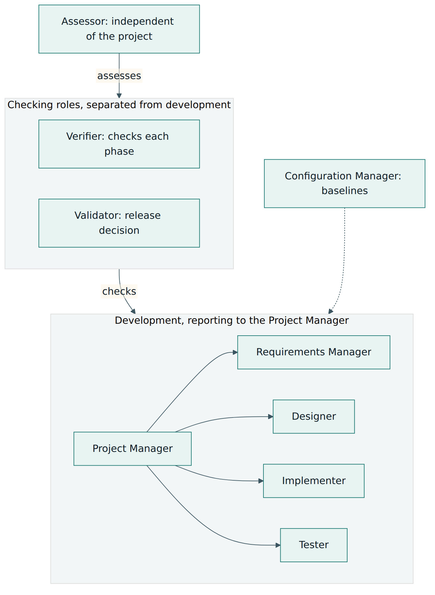
Figure 4 is a simplified picture. In practice, the organisational options for SIL 3 and SIL 4 keep the validator out of the project manager's reporting line and give the validator the authority to stop a release; the verifier must be independent of the people who wrote the requirements, design and code; and the assessor must be independent of the whole project. At lower levels, some roles may be combined or report differently, and the exact permitted combinations are defined in subclause 5.1 for each integrity level. The rewritten clause also addresses commercial and schedule pressure explicitly: independence is meant to protect safety judgements from being overridden by profit or deadlines. Whatever structure is chosen, it is written into the plans and each person's competence is recorded.
Tools and languages
Because tools can introduce faults just as people can, the standard classifies them by how much harm a tool defect could do:
- T1 – tools whose output cannot contribute, directly or indirectly, to the executable code or data, such as a text editor or a requirements management tool.
- T2 – tools that support testing or verification; a fault in them could let a defect go unnoticed but cannot itself put a defect into the executable. Static analysers, test harnesses and coverage tools are typical.
- T3 – tools whose output contributes to the executable code or data, such as compilers, linkers, code generators and data preparation tools.
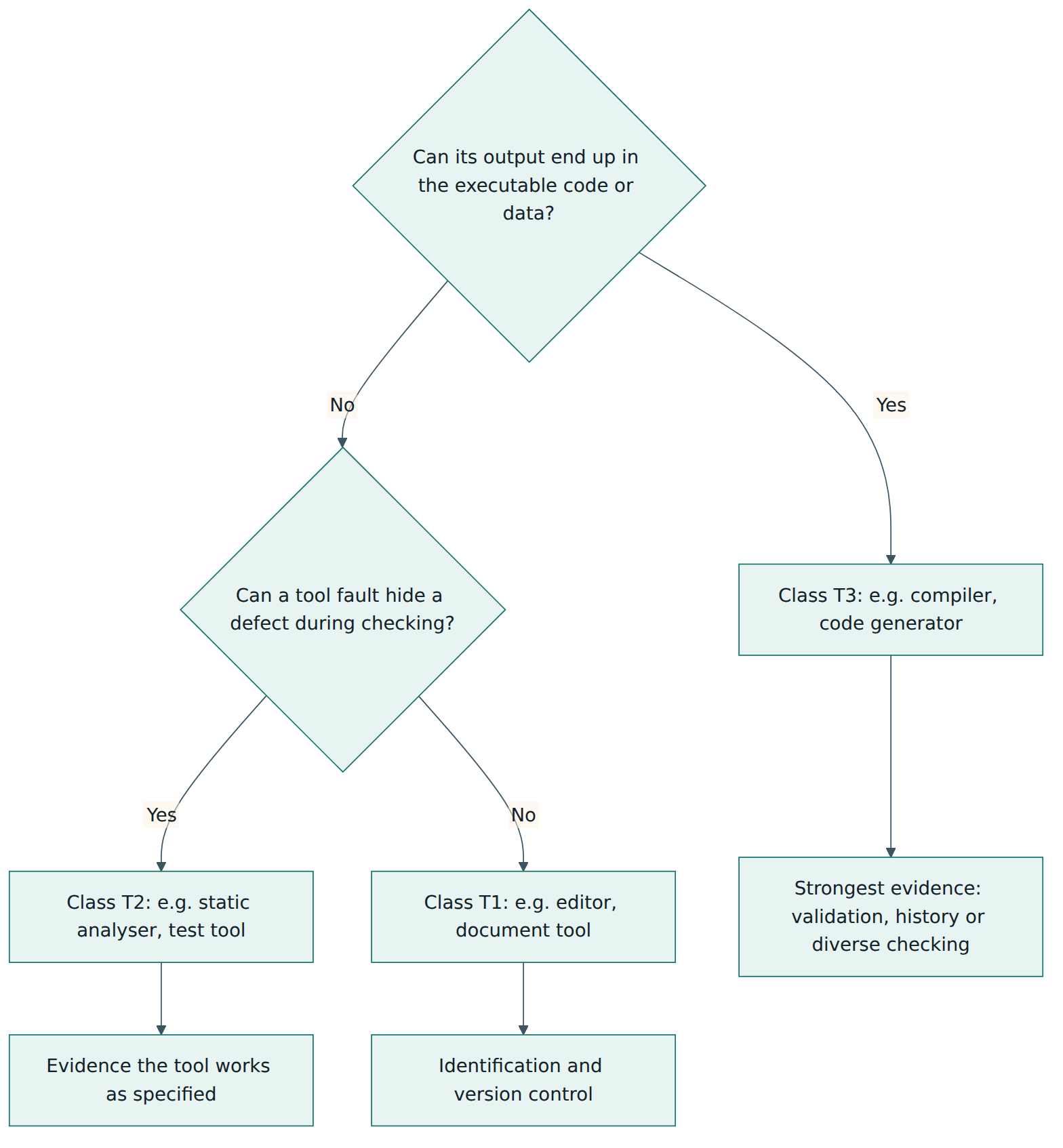
Figure 5 shows the decision. The higher the class, the more evidence is needed that the tool is fit for purpose: a specification or manual, records of its validation, proven use in comparable projects, or a strategy where an independent tool or check catches errors the first tool might introduce. Every tool, whatever its class, must be identified and kept under configuration control so that the exact version used for a release is known. The draft amendment prA1 adds guidance that tools based on machine learning can fall into any class and that cloud-hosted or changing tools need their versions, models and data sets recorded and preserved – useful thinking even before the amendment is final.
Pre-existing software and application data
Reusing software is normal and encouraged, but it must be justified. For pre-existing software the project gathers evidence such as its specification, its known defects and usage history, the checks done to integrate it, and how it is protected against failures elsewhere; the more critical its role, the more evidence is needed. For generic software configured by data, the project plans the application preparation, specifies the application requirements, produces and checks the data with controlled tools, tests the configured system and has it validated and, at SIL 1 and above, assessed. A release note then accompanies the configured application so that the people putting it into service know exactly what they are installing.
Lesson 5 – Assessment, certification and compliance
Three layers of checking
Newcomers often confuse verification, validation and assessment. They are complementary, and each answers a different question.
| Activity | Main question | Who | Typical evidence |
|---|---|---|---|
| Verification | Does each phase output correctly reflect its input? | Verifier | Verification reports per phase, review records, static analysis results, traceability |
| Validation | Does the complete software meet its requirements and suit its intended use? | Validator | Overall test report, validation report with a clear release decision |
| Assessment | Do the software, process and evidence conform to EN 50716 and suit the purpose? | Assessor | Software assessment plan and report |
For SIL 1 to SIL 4 an assessment is required; for Basic Integrity it is not. The assessor examines the plans, the lifecycle records and the product, may carry out audits and inspections, and writes an assessment report that states whether the software conforms and lists any conditions or open points. The assessor is independent of the project; in the railway world this work is often done by an independent safety assessor organisation, although the assessor can also come from another part of a stakeholder's organisation as long as the independence rules are met.
Is there an "EN 50716 certificate"?
EN 50716 does not define a certification scheme of its own, and there is no official register of certified organisations comparable to ISO 9001 certification. What exists in practice is a mix of:
- Assessment reports produced for a specific product or software release, which become part of the system's safety evidence.
- Product or tool certificates that some accredited certification bodies issue, stating that a product, a development process or a support tool has been assessed against the standard for a given integrity level. These are private attestations based on assessment, and their value depends on the scope written on them.
- Personal training certificates from training providers. These show that someone attended a course; the standard itself asks for documented competence per role, not for any particular personal certificate.
Be wary of any claim that a product is "EN 50716 certified" without a clear statement of which software version, which integrity level and which conditions of use were assessed.
How the software evidence is used
Software never goes into service on its own. Its verification, validation and assessment results feed the system safety case, which for signalling is structured according to EN 50129. That safety case is then reviewed in the railway approval process. In the European Union, that process can involve an assessment body applying the common safety method for risk evaluation and assessment, notified bodies checking conformity with the TSIs, and the national safety authority or the EU Agency for Railways authorising vehicles or placing subsystems in service. Annex ZZ explains how the standard supports the essential requirements of the interoperability directive. The software evidence is one important input among many: a perfect software assessment does not compensate for a weak system hazard analysis.
What a good conformity claim contains
A defensible claim of conformity with EN 50716 usually shows: the integrity level and where it came from; the lifecycle followed and the plans that describe it; the selection of Annex A techniques with justifications for every highly recommended technique not used; the organisation with evidence of independence and competence; the complete set of lifecycle documents and verification reports; tool classification and qualification evidence; justification of pre-existing software; validation and test reports; and the assessment report. Many organisations maintain a compliance matrix that maps each requirement of the standard to the project document that satisfies it.
Lesson 6 – Worked example: an object controller for a signalling supplier
Consider a mid-sized supplier, here called Northline Signalling, that develops an electronic object controller. The controller sits at the trackside, receives commands from an electronic interlocking and drives a point machine (moving the switch blades) and reads back the detected position. A wrong position report could let the interlocking set a route over points that are not locked, so the system hazard analysis treats this function as safety critical. The controller also has a maintenance web page that shows diagnostic counters and has no influence on safety.
Step 1 – Start from the system allocation
The system team, following EN 50126, identifies the hazard "train passes points that are not in the commanded and detected position" and allocates SIL 4 to the command and detection function. The diagnostic web page is allocated Basic Integrity, because its failure cannot cause an unsafe state as long as it is isolated from the safety function. The software team does not argue these levels; it receives them as input and records them in the Software Requirements Specification.
Step 2 – Plan the work and the organisation
The quality manager writes the Software Quality Assurance Plan. The team chooses an iterative lifecycle from the Annex C examples: three increments, each delivering a verified set of functions, followed by full integration, validation and assessment of the final release. The plan explains how verification reports are produced at the end of each increment and how earlier evidence is re-checked when later increments change shared code.
Because the core function is SIL 4, the organisation is set up with clear separation. The designers, implementers and tester report to the project manager. The verifier sits in a separate verification team and does not write any of the code or design. The validator reports to the head of the safety department, not to the project manager, and has the authority to refuse a release. An external independent safety assessor is contracted at project start and agrees a software assessment plan, so that assessment runs alongside the project instead of arriving at the end. Each person's competence against the Annex B role descriptions is recorded.
Step 3 – Partition by integrity level
The architecture separates the SIL 4 logic from the Basic Integrity diagnostic page. The SIL 4 part runs on a two-channel processor arrangement where each channel computes the point position and the results are compared; the diagnostic web server runs in a separate partition that can only read a copy of the counters. The architecture document explains why a failure in the web server cannot corrupt the safety function. This is exactly the kind of mixed-integrity argument the new standard gives more guidance on; without it, the whole software would have to be developed at SIL 4.
Step 4 – Select techniques, language and tools
Using the SIL 3–4 column of Annex A, the team selects formal or semi-formal requirements notation for the interlocking interface, a structured design method, defensive programming, a strict coding standard with a restricted language subset, static analysis, boundary value and equivalence class testing, and structural coverage targets agreed with the assessor. For any highly recommended technique it decides not to use, it writes a justification in the plan.
The language is chosen using the criteria in Table A.15 – strong typing, modularity, support for analysis and the availability of a mature compiler – and the decision is documented. Tools are classified: the requirements tool and editor are T1; the static analyser, unit-test framework and coverage tool are T2; the compiler, linker and a code generator used for state machines are T3. For the compiler, the team combines the supplier's validation evidence, a record of extensive use in previous SIL 4 projects and its own test suite run at the object-code level. For the code generator, it adds an independent check: generated code is reviewed and tested exactly like hand-written code, so a generator fault would be caught.
Step 5 – Develop, verify and trace
In each increment, requirements are refined, designs are written and reviewed, code is implemented and tested at component level, and the verifier checks each output against its input. A traceability matrix links every safety requirement to design elements, code units and test cases. Static analysis findings are fixed or justified. Coverage reports show where tests did not reach and lead to new tests or to removal of unreachable code.
Step 6 – Configure for each site
The controller software is generic: for each installation, application data describes which point machine type is connected, its timing limits and its identity in the interlocking. Following clause 8, Northline writes an application preparation plan, prepares the data with a tool that has been classified and qualified, checks the data independently, tests the configured controller on a test rig and issues a release note with each data set. The first site's application is validated and assessed; later sites follow the same proven process with their own checks and records.
Step 7 – Integrate, validate, assess and release
The software is integrated on the real hardware, then tested against the full requirements in a laboratory that simulates the interlocking and the point machine, including fault injection such as lost messages and contradictory detection signals. The validator reviews the results and signs the validation report. The assessor reviews the evidence and issues a report confirming conformity with EN 50716 at SIL 4 for this release, with two conditions of use. The software evidence becomes part of the controller's generic product safety case under EN 50129.
Step 8 – Maintain safely
A year later, a customer asks for a change to the movement timeout. Under subclause 9.2, the change request triggers an impact analysis that identifies the affected requirements, code and tests. The modification is made, regression tests are rerun, the verifier and validator update their reports and the assessor reviews the change. Only then is the new release deployed, with release notes describing exactly what changed.
This example shows the standard's main ideas working together: the integrity level from the system process, a documented plan, separation of roles, scaled techniques, controlled tools, explicit handling of data, independent checking and controlled change.
Lesson 7 – Relationship to other standards and frameworks
EN 50716 is one piece of a family. Knowing its neighbours prevents two common mistakes: expecting it to do the system safety job, and ignoring requirements that come from somewhere else.
| Standard | Focus | Relationship to EN 50716 |
|---|---|---|
| EN 50126-1 and EN 50126-2 (2017) | Railway RAMS: system lifecycle, hazard analysis, risk acceptance, allocation of safety requirements | Provides the system context and the integrity level that EN 50716 takes as input; EN 50716 is aligned with its terms |
| EN 50129 (2018) | Safety-related electronic systems for signalling, safety case structure, hardware integrity | Receives the software evidence into the safety case; also gives guidance for programmable logic devices that EN 50716 excludes |
| EN 50128:2011 and EN 50657:2017 | Earlier software standards for signalling and for rolling stock | Superseded by EN 50716, which keeps their numbering where possible |
| IEC 62279 | International counterpart of EN 50128 for railway software | Similar approach at international level; projects outside Europe may cite it, so check which document a contract names |
| IEC 61508-3 | Generic software requirements for functional safety in any industry | The cross-sector parent of the railway approach; useful background, but rail projects apply the sector standard |
| CLC/TS 50701 and IEC 62443 | Railway and industrial cybersecurity | Applied alongside EN 50716, which does not cover security measures but recognises that attacks can affect safety |
| ISO 9001 | General quality management systems | A sound quality management system supports every integrity level, especially Basic Integrity |
Safety and security together
One relationship deserves attention. Security often calls for rapid patching when a vulnerability is found, while safety calls for careful development, testing, validation and approval of every change. EN 50716 explicitly recognises this tension. A good project decides in advance how security updates will be analysed for safety impact, how much regression testing they need and how they are approved, so that neither concern blocks the other.
Other sectors
Engineers coming from road vehicles (ISO 26262), aviation (DO-178C) or medical devices (IEC 62304) will recognise the pattern: integrity levels derived from system risk, a defined lifecycle, techniques scaled to criticality, tool qualification and independent review. The vocabulary and details differ – rail uses SIL 1–4 plus Basic Integrity and has a strong tradition of independent safety assessment and safety cases – so mapping between standards should be done carefully rather than assumed.
Common pitfalls and best practices
Common pitfalls
- Choosing the integrity level inside the software team. The level must come from the system risk analysis; a software team that picks its own level, usually lower, undermines the whole argument.
- Treating it as a document factory. Producing every listed document while the engineering behind them is weak gives assessors paperwork, not confidence. Documents should record real decisions and real checks.
- Bringing in the assessor at the end. An assessor who sees the project only at release time often finds structural gaps that are expensive to fix. Agree the assessment plan early.
- Ignoring tool classification. Using an unqualified code generator or compiler for safety software leaves an unexplained path for faults into the executable.
- Weak independence in practice. A validator who formally sits in another department but depends on the project manager for bonus or workload is not truly independent.
- Forgetting application data. Treating site configuration as "just data" and not as a controlled engineering product is a well-known way for errors to reach a safety function unchecked.
- Assuming agile is forbidden or that agile means less evidence. Iterative lifecycles are allowed, but each increment must still produce verifiable evidence and the final release must be validated and assessed as a whole.
Best practices
- Write the plans first and keep them alive. A clear quality assurance plan with justified technique choices is the anchor for everything that follows; update it when the project changes.
- Build traceability from day one. Link requirements, design, code and tests in a tool as you go, so verification and impact analysis are quick and complete.
- Partition by integrity level deliberately. Isolating low-integrity functions saves effort, but only if the architecture argument for isolation is explicit and verified.
- Keep a compliance matrix. Map each requirement and table entry of the standard to the evidence that satisfies it; assessors and future maintainers will thank you.
- Invest in competence. Record training and experience against the role descriptions and plan how newcomers gain the needed skills under supervision.
- Automate checking. Static analysis, automated regression tests and coverage measurement in a continuous integration pipeline make repeated verification across iterations affordable.
- Plan for maintenance and security updates. Decide early how changes will be analysed, tested and approved over the decades a railway system stays in service.
Summary and key takeaways
- EN 50716:2023 is the single CENELEC standard for developing, deploying and maintaining software for railway signalling and on-board rolling stock systems; it supersedes EN 50128 and EN 50657, with the transition period ending on 30 October 2026.
- Its central idea is the software integrity level – Basic Integrity and SIL 1 to SIL 4 – which comes from the system risk analysis under EN 50126 and decides techniques, independence and assessment.
- The normative Annex A tables rate techniques as mandatory, highly recommended, recommended, neutral or not recommended; SIL 1–2 and SIL 3–4 share technique sets, and skipped highly recommended techniques need justification.
- Annex B defines nine roles; checking roles are separated from development roles, and the separation becomes stricter at higher integrity levels.
- Verification checks each phase, validation confirms fitness of the whole, and independent assessment, required for SIL 1–4, judges conformity of the software and its evidence.
- Support tools are classified T1, T2 or T3 according to their possible effect on the executable, and need correspondingly stronger evidence.
- Iterative lifecycles, modelling, pre-existing software and data-configured generic software are all accommodated, provided the evidence is planned and complete.
- The software evidence feeds the system safety case and the railway approval process; it is necessary but never sufficient on its own.
Reflection questions
- Think of a railway or other safety-related product you know. Which of its software functions would likely need a high integrity level, which could be Basic Integrity, and what architectural measures would let you keep them apart?
- Your organisation uses two-week sprints. How would you adapt its way of working so that every increment produces the evidence EN 50716 expects without slowing delivery unnecessarily?
- List the tools in your current development pipeline. How would you classify each one as T1, T2 or T3, and what evidence would you need for the T3 tools?
- How would you set up reporting lines and incentives so that a validator can refuse a release under schedule pressure without personal risk?
- A critical security vulnerability is found in a library used by SIL 2 software already in service. Describe the steps you would take to balance a fast fix with the safety change process.
Further reading and official sources
- EN 50716:2023 Railway Applications – Requirements for software development (catalogue entry) – CENELEC, via iTeh Standards
- EN 50716:2023/prA1 draft amendment on AI and machine learning (catalogue entry) – CENELEC, via iTeh Standards
- CEN and CENELEC – European standardisation organisations – CEN-CENELEC
- New standard EN 50716:2023 – Requirements for software development, Part 1 – CSA Engineering
- New standard EN 50716:2023 – Requirements for software development, Part 2 – CSA Engineering
- A guide on CENELEC EN 50716 – Prover
- CENELEC is amending EN 50716 for AI: what the draft says – Prover
- From EN 50128 to EN 50716: railway software compliance – QA Systems
Original tutorial by xOps School (DevOpsSchool Private Limited), written from public sources about EN 50716. Not affiliated with or endorsed by the standard's owner; standard names are trademarks of their owners. Buy the official standard from its publisher for the authoritative text.