
IEC 61508 – Tutorial (about 60 minutes)
- View
IEC 61508 is the international "umbrella" standard for functional safety: the part of overall safety that depends on electrical, electronic and programmable electronic systems doing the right thing when something goes wrong. It is used by manufacturers of safety controllers, sensors and valves, by machine and plant builders, by assessors and certification bodies, and by the committees that write sector standards for process plants, machinery, railways, nuclear plants and cars. After this tutorial you will be able to explain what the standard covers, read its seven-part structure, follow the safety lifecycle from hazard analysis to decommissioning, interpret a safety integrity level (SIL), and recognise what an honest claim of compliance looks like.
Course overview
Edition and status: the current edition is IEC 61508:2010, Edition 2.0, Functional safety of electrical/electronic/programmable electronic safety-related systems, Parts 1 to 7, published by the International Electrotechnical Commission (IEC) on 30 April 2010 and maintained by technical committee TC 65, subcommittee SC 65A (system aspects). It replaced the first edition of 1998–2000. The IEC webstore lists a stability date of 2027 for the 2010 parts, and IEC also sells a "commented version" that shows the changes from the first edition. Edition 3 is being prepared but is not published: a committee draft has been circulated and commented on, the next stage is a committee draft for vote, and the 61508 Association expects the third edition to become available in early 2027. Until it is published, Edition 2.0 is the edition to apply and the one this course teaches; details of the new edition may still change. Verified 2026-10-29 against the IEC webstore entries for IEC 61508-1, -2, -3 and -5:2010 and the commented version, and the 61508 Association's standards-development page.
Who it is for: engineers (electrical, control, software, hardware, reliability), product managers, quality and safety staff, project managers and buyers who meet IEC 61508 for the first time, for example because a customer asks for a "SIL 2" product, because a plant needs a safety shutdown system, or because a sector standard they use is built on IEC 61508.
Prerequisites: none. A basic idea of how a control system works (sensors measure, a controller decides, actuators act) helps. Probability is used lightly and every term is explained when it first appears.
By the end of this tutorial:
- You will be able to explain what functional safety is, why IEC 61508 exists and how it relates to sector-specific standards.
- You will be able to define the core vocabulary: safety function, equipment under control, safety integrity, SIL, demand mode, random and systematic failures, hardware fault tolerance and safe failure fraction.
- You will be able to describe the purpose of each of the seven parts and find where a topic is handled.
- You will be able to walk through the overall safety lifecycle and name the main documents and roles.
- You will be able to explain the three conditions a design must meet before it can claim a SIL.
- You will be able to judge a compliance or certification claim and know what evidence to ask for.
- You will be able to place IEC 61508 next to IEC 61511, IEC 62061, ISO 26262 and other related standards.
Lesson 1 – Origins, purpose and scope
Why a standard about "functional" safety?
Many dangers in industry are managed by physical design: a thick vessel wall, a guard around a blade, a relief valve that opens mechanically. But a growing share of protection is provided by electronics and software. A gas detector shuts a valve; a light curtain stops a press; a controller cuts power to a heater when a temperature climbs too high. In each case, safety depends on a system functioning correctly in response to its inputs. If the sensor drifts, the processor crashes, the software has a logic error or the output relay welds shut, the protection silently disappears. Functional safety is the name for this slice of safety: freedom from unacceptable risk that relies on safety-related systems and other risk-reduction measures working as intended.
Before the 1990s, rules for electronic protection systems varied widely between countries and industries, and many safety engineers distrusted programmable devices altogether. Programmable electronics, however, offered better diagnostics, flexibility and cost. The industry needed a common, technology-neutral way to answer a simple question: how good does a protection system have to be, and how do we show that it is good enough? IEC work on this began in the 1980s, drafts circulated as "IEC 1508", and the first edition of IEC 61508 was published between 1998 and 2000. The second edition of 2010 clarified many requirements, tightened the treatment of hardware architecture and software, and added points such as considering malicious threats during hazard analysis.
Two key ideas
The whole standard rests on two ideas. First, zero risk is not achievable; the aim is to reduce risk to a level that is tolerable for the situation, and to do so in a planned, justified way. Second, failures come in two flavours that need different treatment. Some failures happen at random, as physical components wear out or are stressed; these can be estimated with probabilities. Others are built in by mistakes in specification, design, software, manufacture, installation or maintenance; these cannot be predicted with statistics and must be prevented by a disciplined process. IEC 61508 therefore combines numerical targets for random hardware failures with process requirements for avoiding and controlling systematic failures.
Scope
The standard applies to safety-related systems that contain at least one electrical, electronic or programmable electronic element. That covers anything from a simple relay circuit to a networked safety controller with millions of lines of code. It is generic: it does not mention any particular industry, hazard or product. It covers the entire life of the system, from the first concept through hazard analysis, specification, design, installation, operation, maintenance, modification and finally decommissioning.
IEC 61508 is designed to be used in two ways. It can be applied directly, for example by a manufacturer of a safety relay or a smart transmitter that will be sold into many industries, or by a project in a sector that has no specific standard of its own. It is also a basic safety publication: a reference that IEC committees use when writing sector standards. That is why the process industry (IEC 61511), machinery (IEC 62061), nuclear instrumentation (IEC 61513) and road vehicles (ISO 26262) all have functional safety standards that share its concepts and vocabulary while adapting the details to their own world.
Some boundaries are worth knowing early. IEC 61508 addresses hazards caused by failures of the safety-related system to perform its function. Hazards such as electric shock from the equipment itself, fire from overheated wiring or electromagnetic emissions are handled by other product safety standards. The standard does not decide what level of risk society accepts; that is a matter for regulators, sector bodies and the organisation. And while the 2010 edition asks for security threats to be considered in the hazard analysis, detailed security engineering belongs to standards such as IEC 62443.
Lesson 2 – Key concepts and vocabulary
IEC 61508 has its own vocabulary, defined in Part 4. The terms below are explained in plain words; they are not the official definitions. Learning them well is half the work, because sector standards reuse most of them.
- Equipment under control (EUC) – the machine, process, plant or apparatus whose hazards you are trying to manage, for example a chemical reactor, a press or a furnace.
- EUC control system – the normal control system that makes the EUC do its job (keeps temperature at setpoint, runs the press cycle). It is usually not counted as safety-related unless it is designed to meet the standard.
- Safety function – a specific function, implemented by a safety-related system or other measure, that achieves or keeps a safe state for the EUC in response to a particular hazardous event. Example: "If the furnace temperature exceeds the trip limit, cut the heater power within five seconds."
- E/E/PE safety-related system – an electrical, electronic or programmable electronic system that implements one or more safety functions, typically consisting of sensors, a logic solver and final elements (actuators such as valves, contactors or brakes).
- Safety integrity – how likely it is that a safety-related system carries out its safety functions correctly, under the conditions specified, over a defined period of time. It has a hardware part (random failures) and a systematic part (built-in faults).
- Safety integrity level (SIL) – one of four discrete levels, SIL 1 (lowest) to SIL 4 (highest), used to specify how much safety integrity a safety function needs. Each level corresponds to a band of target failure measures.
- Demand – an event that calls on the safety function to act, such as the temperature actually reaching the trip limit.
- Low demand mode – the safety function is required to act no more than once per year; it sits waiting most of the time, like an emergency shutdown. Its target measure is the average probability of dangerous failure on demand (PFDavg).
- High demand or continuous mode – the function is demanded more than once per year or operates all the time, like a brake control or a guard interlock on a machine used all day. Its target measure is the average frequency of dangerous failure per hour (PFH).
- Random hardware failure – a failure at an unpredictable time from physical degradation of hardware; its rate can be estimated from reliability data.
- Systematic failure – a failure related deterministically to a cause such as a specification error, a design mistake, a software bug or a wrong procedure; it will happen every time the same conditions occur, and it can only be removed by changing the design, process or documentation.
- Dangerous and safe failures – a dangerous failure stops the safety function from acting when needed (or makes it act wrongly in an unsafe way); a safe failure tends to cause a spurious trip or has no effect on safety. Dangerous failures are split into "detected" (found by diagnostics) and "undetected".
- Diagnostic coverage (DC) – the fraction of dangerous failures that automatic diagnostic tests detect.
- Proof test – a periodic test, often manual, that reveals dangerous failures the diagnostics cannot see, so that the system can be repaired to an "as new" condition.
- Hardware fault tolerance (HFT) – the number of hardware faults a subsystem can have while still performing its safety function. HFT 0 means a single fault can defeat it; HFT 1 means two faults are needed.
- Safe failure fraction (SFF) – the share of all failures of an element that are either safe or dangerous-but-detected. A high SFF means few failures are both dangerous and hidden.
- Common cause failure – a single cause (heat, a design error, a wrong calibration) that makes two or more redundant channels fail together, defeating the redundancy.
- Tolerable risk and residual risk – tolerable risk is the level of risk judged acceptable in a particular situation, reflecting what society currently expects; residual risk is the risk that remains after all protective measures.
- Systematic capability (SC) – a measure, on a scale of 1 to 4, of the confidence that an element's systematic safety integrity is good enough for a given SIL.
Two more ideas are worth clarifying. Redundant architectures are described with "M out of N" (MooN) notation: 1oo2 means two channels where either one can trip the system; 2oo3 means three channels where any two must agree. And a SIL is always a property of a safety function, never of a single product on its own. A pressure transmitter can be "suitable for use in SIL 2 safety functions" within limits stated in its documentation, but it is the complete loop of sensor, logic and final element that achieves a SIL.
The SIL bands
The target failure measures for each SIL are numerical ranges. For a function in low demand mode the PFDavg bands are: SIL 1 from 10⁻² up to 10⁻¹, SIL 2 from 10⁻³ up to 10⁻², SIL 3 from 10⁻⁴ up to 10⁻³, and SIL 4 from 10⁻⁵ up to 10⁻⁴. Put simply, a SIL 2 function in low demand mode should fail to act on fewer than one demand in a hundred, on average, and better than one in a thousand would place it in the SIL 3 band. For high demand or continuous mode, the PFH bands run from 10⁻⁶ up to 10⁻⁵ dangerous failures per hour for SIL 1 down to 10⁻⁹ up to 10⁻⁸ for SIL 4. Each step up a SIL is a factor of ten in the risk reduction the function must deliver.
| SIL | Low demand: PFDavg band | Equivalent risk reduction factor | High demand / continuous: PFH band (per hour) |
|---|---|---|---|
| 4 | 10⁻⁵ to < 10⁻⁴ | above 10,000 up to 100,000 | 10⁻⁹ to < 10⁻⁸ |
| 3 | 10⁻⁴ to < 10⁻³ | above 1,000 up to 10,000 | 10⁻⁸ to < 10⁻⁷ |
| 2 | 10⁻³ to < 10⁻² | above 100 up to 1,000 | 10⁻⁷ to < 10⁻⁶ |
| 1 | 10⁻² to < 10⁻¹ | above 10 up to 100 | 10⁻⁶ to < 10⁻⁵ |
The numbers apply to random hardware failures. Systematic failures cannot be counted this way, so for them the SIL instead selects how rigorous the techniques and measures must be: higher SILs need more formal specifications, more independent reviews, stronger testing and tighter change control.
Lesson 3 – Structure of the standard
IEC 61508 is published as seven parts, plus an informative technical report sometimes called "Part 0". The first four parts carry the normative requirements and hold basic safety publication status; Parts 5, 6 and 7 are informative and give guidance, examples and descriptions of techniques. The overview below is paraphrased.
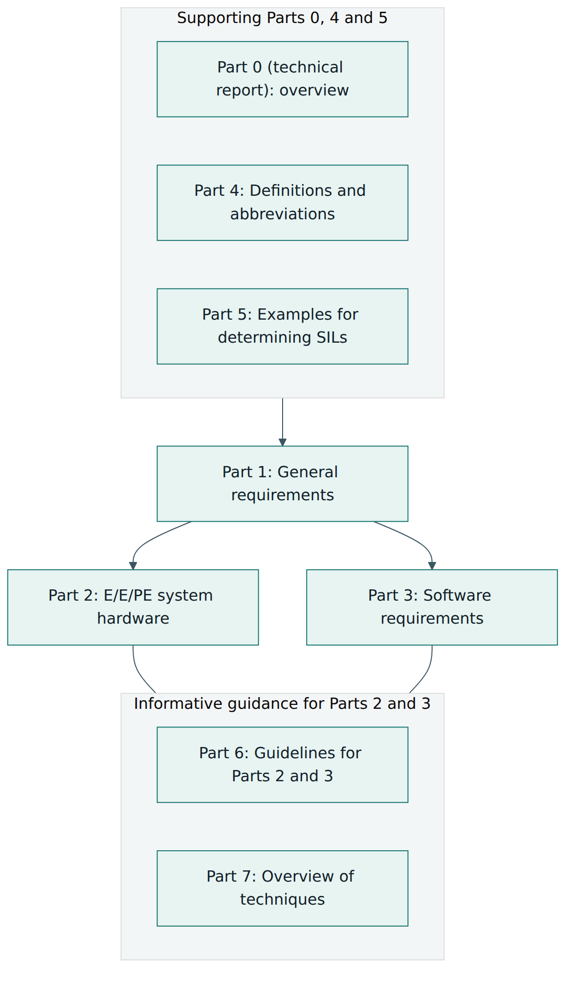
Part 1 – General requirements
Part 1 is the backbone. It defines the overall safety lifecycle and what each phase must achieve, how to perform hazard and risk analysis, how to specify overall safety requirements and allocate them to safety functions with SILs, and how to plan operation, maintenance, installation and validation. It also contains the management requirements that apply throughout: documentation, management of functional safety (responsibilities, planning, configuration and change control), competence of people, verification, functional safety audits and functional safety assessment, including the degree of independence the assessor must have.
Part 2 – Requirements for E/E/PE safety-related systems
Part 2 deals with the hardware and the system as a whole, excluding software. It explains how to turn the safety requirements into a system design, how to meet the target failure measure, which architectural constraints apply (hardware fault tolerance and safe failure fraction), how to control and avoid systematic faults in hardware, how to handle data communication used for safety, and what information a supplier must provide in a safety manual for a "compliant item" sold for use in safety functions. It also covers installation, commissioning and validation of the E/E/PE system and requirements for organisations that later modify it.
Part 3 – Software requirements
Part 3 applies to any software that is part of a safety-related system or used to develop one, including embedded firmware, application programs and tools such as compilers. It defines a software safety lifecycle that mirrors the system lifecycle: software safety requirements, architecture, design, coding, module testing, integration testing, validation and modification. Its annexes recommend techniques and measures graded by SIL, such as structured design methods, coding standards, static analysis, defined test coverage and, at higher SILs, formal or semi-formal methods. A recommendation in these tables is not a free choice: if you depart from a highly recommended technique you must justify why.
Part 4 – Definitions and abbreviations
Part 4 provides the vocabulary used everywhere else. Many sector standards borrow it.
Part 5 – Examples of methods for determining safety integrity levels
Part 5 is informative. It explains the concepts of risk, tolerable risk and necessary risk reduction, and the "as low as reasonably practicable" (ALARP) principle used in some countries. It then shows example methods for deciding which SIL a safety function needs: quantitative calculations, risk graphs (decision trees based on consequence, exposure, possibility of avoidance and demand rate), severity matrices and layer of protection analysis (LOPA). None of these methods is mandatory; the organisation must calibrate whatever method it uses to its own tolerable-risk criteria.
Part 6 – Guidelines on the application of Parts 2 and 3
Part 6 is also informative. It gives worked approaches for calculating PFDavg and PFH for common architectures, a method for estimating common cause failures (the "beta factor" approach), and examples of applying the software requirements.
Part 7 – Overview of techniques and measures
Part 7 briefly describes each technique named in the tables of Parts 2 and 3: what it is, what it aims at and where to read more. When a table recommends, for instance, "boundary value analysis" or "program sequence monitoring", Part 7 explains what that means.
Supporting documents
The technical report IEC TR 61508-0 gives an informal overview of functional safety and the series. Like the commented version mentioned in the course overview, such supporting documents help interpretation but do not change the requirements of the 2010 parts.
Lesson 4 – How it works in practice
The overall safety lifecycle
The heart of IEC 61508 is the overall safety lifecycle in Part 1: a sequence of 16 phases that takes a system from idea to disposal. Each phase has defined inputs, objectives, requirements and outputs, so that nothing is left to chance and every decision can be traced. The phases fall into three groups: analysis (understanding the hazards and deciding what protection is needed), realisation (building the protection) and operation (keeping it effective).
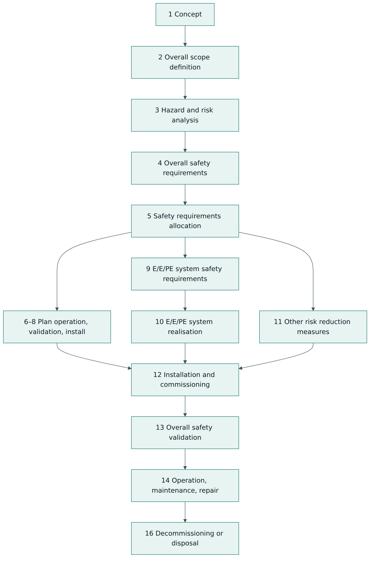
Phase 15, overall modification and retrofit, is not drawn as a box above but is always present: any change during operation sends you back to the lifecycle phase affected by the change, with an impact analysis first. The phases in plain words:
- Concept and scope (phases 1–2): understand the EUC, its environment and the boundaries of the analysis.
- Hazard and risk analysis (phase 3): identify hazards and hazardous events in all reasonably foreseeable circumstances, including fault conditions and misuse, and estimate the associated risk. The 2010 edition expects this analysis to consider malicious threats as well; where they are credible, a security threat analysis should follow.
- Overall safety requirements and allocation (phases 4–5): state which safety functions are needed and how much risk reduction each must provide, then allocate them to E/E/PE safety-related systems or to other risk reduction measures (mechanical devices, physical barriers, procedures), assigning a SIL to each function given to an E/E/PE system.
- Planning (phases 6–8): plan how the system will be operated and maintained, validated and installed, before you build it, so that test points, access and proof testing are designed in.
- Realisation (phases 9–11): write the E/E/PE system safety requirements specification, then design and build the system (applying Part 2 for hardware and Part 3 for software) and realise any other measures.
- Installation, commissioning and validation (phases 12–13): install the system, then confirm that the whole installation meets the overall safety requirements.
- Operation, modification and decommissioning (phases 14–16): run, proof-test, repair and change the system under control, and remove it safely at end of life.
Risk reduction and allocation
The logic linking hazard analysis to SIL is simple once you see it. The EUC (with its normal control system) carries a certain risk if nothing else protects it. Society, regulators or the organisation set a tolerable level. The gap between the two is the necessary risk reduction. That reduction can be shared between several protection layers: the E/E/PE safety-related system, safety-related systems based on other technologies (a mechanical relief valve, a rupture disc) and external measures (a bund, an evacuation plan). Whatever is assigned to the E/E/PE safety function determines its SIL.
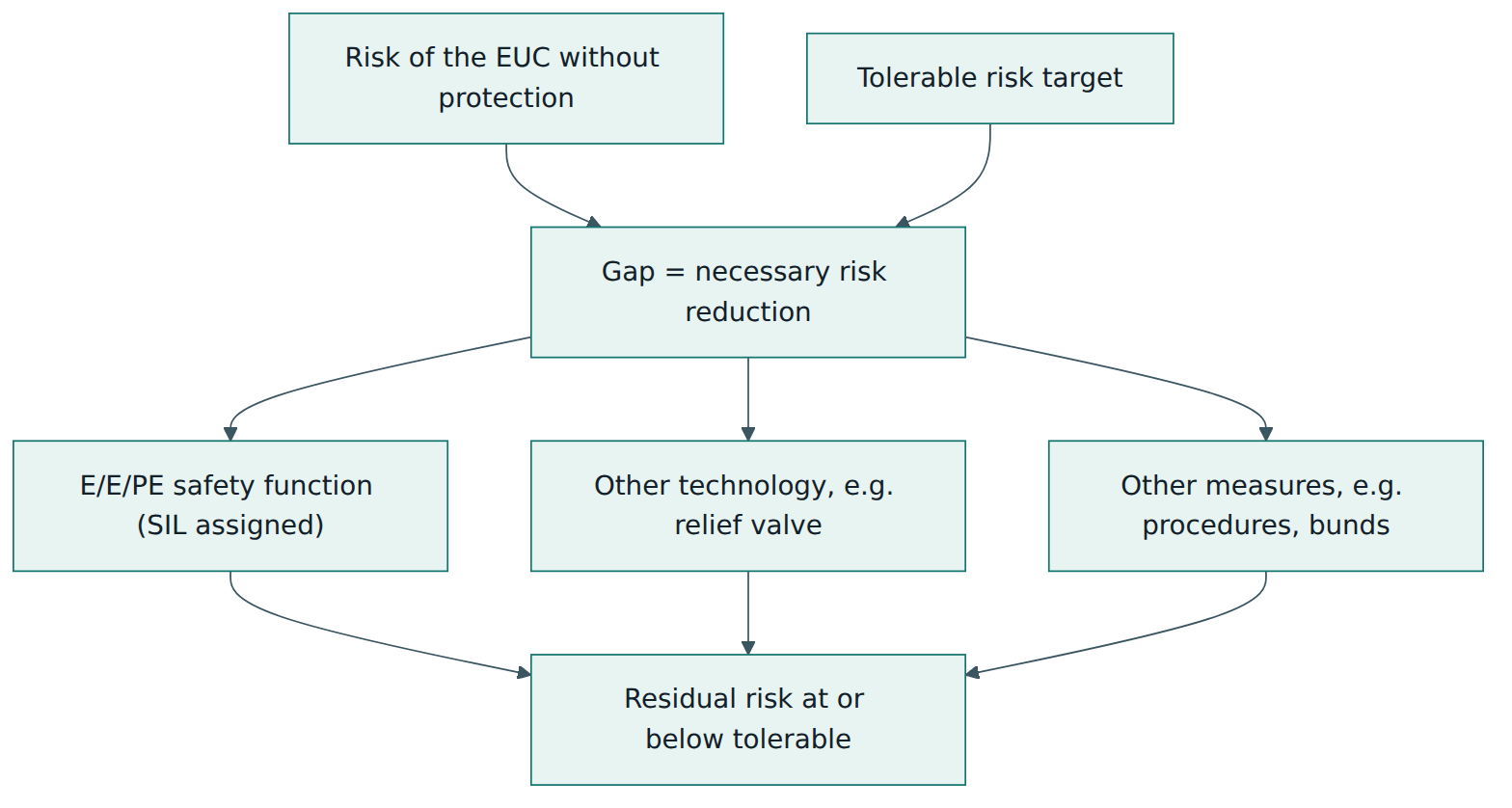
A subtle consequence: if more risk reduction can be obtained from simpler means, such as a mechanical device or a change to the process, the SIL demanded of the electronics falls. Good designers look for inherent safety first and treat the SIL as the result of a design choice, not an unavoidable fact.
Three conditions for meeting a SIL
Once a safety function has a SIL target, Part 2 and Part 3 require the implementing system to satisfy three separate conditions. Meeting one is not enough; the SIL that can be claimed is limited by the weakest of the three.
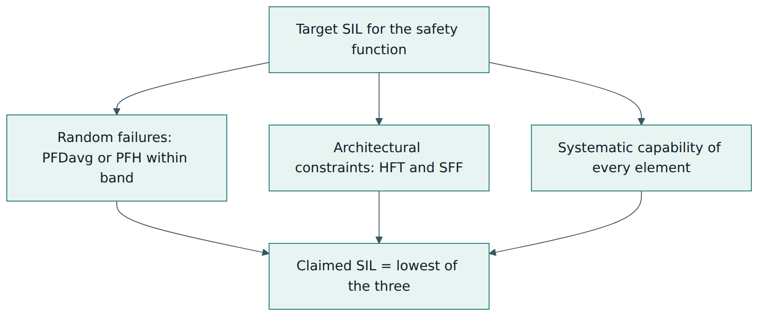
- Quantified random failures. Using failure rates, diagnostic coverage, proof test intervals, repair times and common cause factors, you calculate PFDavg or PFH for the whole function (sensor subsystem plus logic plus final elements) and show it lies in the required band. A useful rough model for a single channel in low demand mode is that PFDavg is about the undetected dangerous failure rate multiplied by half the proof test interval, which shows why longer test intervals raise the failure probability.
- Architectural constraints. Calculations depend on data that may be optimistic, so the standard also sets minimum robustness. Under "Route 1H", tables relate the hardware fault tolerance, the safe failure fraction and the element type to the highest SIL that can be claimed. Type A elements are simple, with well-understood failure modes and solid field data (a resistor, a relay); Type B elements are complex, with less predictable behaviour (anything containing a microprocessor). Under "Route 2H", the constraints are based on reliability data collected from field experience with stated confidence, combined with minimum fault tolerance requirements per SIL.
- Systematic capability. Every element must have a systematic capability at least equal to the target SIL, or be combined so that the design compensates. For new hardware and software this is achieved by following the techniques and measures for that SIL ("Route 1S"). For existing elements, evidence of "proven in use" ("Route 2S") may be accepted if the operating history is well documented and relevant. Part 3 adds a third route for pre-existing software that was not developed to the standard ("Route 3S"), where it must be assessed against the same objectives.
Software development in practice
Part 3 is often summarised as a V-model. The left side goes down from software safety requirements to architecture, design and code; the right side goes up from module tests to integration tests and validation against the requirements. Every arrow across the V is a verification step. The software requirements must be traceable to the system safety requirements, and every test traceable back to a requirement. The standard distinguishes the languages used: application programs in a safety PLC are usually written in a "limited variability language" (such as ladder logic or function blocks with a restricted set of certified functions), which carries lower risk than general-purpose code in C for embedded firmware. Tool qualification matters too: tools are classified by how much they could introduce errors into the executable code, and the more influence a tool has, the more evidence of its suitability you need.
Roles and key artefacts
The standard assigns responsibility to organisations and people rather than prescribing job titles, but most projects include these roles: a person accountable for functional safety management, safety engineers who perform the analyses, hardware and software developers, verifiers, validators and an assessor with the required independence. The typical documents are:
- a functional safety plan or management plan describing activities, responsibilities, competence and schedule;
- the hazard and risk analysis report, with assumptions and the tolerable-risk criteria used;
- the overall and E/E/PE system safety requirements specifications, listing each safety function, its SIL, mode, response time and safe state;
- design documents, failure modes effects and diagnostic analysis (FMEDA) results and reliability calculations;
- software safety requirements, design, code review and test records;
- verification and validation plans and reports;
- the safety manual for each compliant item (operating limits, diagnostics, proof test procedures, failure data, constraints of use);
- operation and maintenance procedures, proof test records and a modification log;
- functional safety assessment and audit reports.
Competence is a requirement, not a nice-to-have. Part 1 asks that everyone with responsibility for safety activities is competent for their duties, considering their training, experience, the novelty and complexity of the application, and the consequences of error.
Lesson 5 – Assessment, certification and compliance
Verification, validation, audit and assessment
These four activities are often confused, but IEC 61508 keeps them apart:
- Verification checks that each phase's outputs meet the requirements of that phase (did we build this step right?). Reviews, analyses and tests at every lifecycle stage are verification.
- Validation confirms that the finished system meets its safety requirements specification in its intended environment (did we build the right thing?).
- Functional safety audit examines whether the procedures required by the safety plan were actually followed.
- Functional safety assessment (FSA) is an investigation, based on evidence, that reaches a judgement on the functional safety achieved by the system. It is required for every SIL and may be carried out after each phase or at defined points.
Independence
Part 1 specifies the minimum independence of the people carrying out the FSA, graded by the SIL and by the consequences of failure. The three levels are an independent person (not involved in the design), an independent department (separate from the design department) and an independent organisation (a separate company or a separate legal and management structure). The higher the SIL and the more severe the possible consequences, the more independence is needed. A project team cannot assess its own work at the higher levels, however competent it is.
Is there an "IEC 61508 certificate"?
IEC writes standards; it does not certify products, people or companies against IEC 61508. What exists in the market are third-party assessments and certificates issued by certification bodies and specialist assessors, often accredited by national accreditation bodies for product certification. They typically certify:
- products ("compliant items") such as safety PLCs, transmitters, valves and relays, stating the maximum SIL in which the item may be used, its systematic capability, failure data and the conditions in its safety manual;
- development processes, confirming that a company's functional safety management system can produce products to a stated SIL;
- people, through personnel competence programmes for engineers and assessors; these are private schemes, not official IEC qualifications.
A certificate is a useful piece of evidence but not the whole story. It applies to a specific product version, under specific conditions. A system integrator who uses a certified logic solver still has to design, verify and validate the complete safety function, respect the safety manual, and carry out the calculations for the whole loop. Conversely, a product does not need a certificate to be used in a safety function; the user can assess the evidence directly, provided the competence and independence requirements are met.
Legal and regulatory status
IEC 61508 is a voluntary standard. It becomes binding through contracts, through sector standards that reference it, or through regulators who treat it as recognised good practice. In the European Union the standard has been adopted as the EN 61508 series, and other regions have national adoptions.
What good evidence looks like
An assessor typically wants to see a traceable chain: the hazard and the risk target lead to a safety function with a SIL; the function is described in the safety requirements specification; the design shows architecture, failure data, calculations and systematic capability for every element; verification records show each step was checked; validation records show the installed system works; and operation records show proof tests are done and failures are analysed.
Lesson 6 – Worked example
This example is fictional and simplified. The numbers illustrate the method; they are not design data for a real system.
The situation
Ferrotherm is a small company that builds electric heat-treatment furnaces for metal parts. A customer in the aerospace supply chain asks for a furnace with an independent over-temperature protection, "designed to IEC 61508". There is a normal temperature controller, but if it fails high (a stuck output, a thermocouple fault) the chamber could overheat, the load could ignite residual quench oil, and an operator near the door could be seriously burned. Ferrotherm has not done IEC 61508 work before. It appoints a functional safety manager, writes a functional safety plan and engages an external assessor early.
Step 1 – Scope and hazard analysis
The team defines the EUC as the furnace chamber, heaters, door, quench area and normal control system. In a workshop using a hazard and operability style review, it lists hazardous events: over-temperature from a controller failure, door opening at high temperature, loss of cooling water and others. It also notes that the control panel has a remote maintenance connection, so a security threat analysis is added to the plan. For over-temperature, the estimated demand rate on any protection is about once every ten years, mainly from controller failures, so this is a low demand situation.
Step 2 – Required risk reduction and SIL
Ferrotherm uses a calibrated risk graph from its customer's corporate safety standard, of the kind described in Part 5. Considering serious injury, frequent presence of an operator, a low possibility of avoiding the event and the expected demand rate, the graph points to SIL 2. The team checks the result with a simple LOPA: the unprotected event frequency of about 0.1 per year, combined with the probability of ignition and of a person being present, must be reduced by a factor of more than 100 to meet the customer's tolerable frequency. A mechanical thermal fuse in the heater circuit was considered as an extra layer, but it could not be tested in place, so the team decided not to credit it. The safety function is written as SF-01: "When the chamber temperature exceeds 950 °C, de-energise all heater circuits within 5 seconds and hold them off until a manual reset." Required SIL: 2, low demand mode.
Step 3 – Safety requirements specification
The specification records the trip point, the response time, the safe state (heaters off), the manual reset, the behaviour on detected faults (trip and alarm), the proof test interval (one year, aligned with the annual maintenance shutdown), the environmental conditions, the independence from the normal controller (separate sensors, separate logic, separate contactors) and the spurious trip rate the customer can accept.
Step 4 – Architecture and element selection
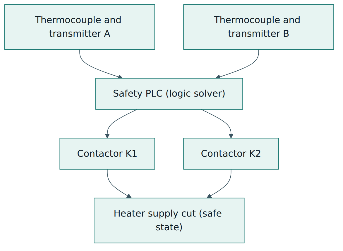
- Sensors: two thermocouples with temperature transmitters that come with a safety manual and failure data, voted 1oo2 so either can trip. The transmitters are Type B with a safe failure fraction above 90 %, and the 1oo2 arrangement gives a hardware fault tolerance of 1.
- Logic solver: a safety PLC certified by a third party as suitable for SIL 3, with systematic capability SC 3 and internal redundancy and diagnostics.
- Final elements: two contactors wired in series, each able to cut the heater supply alone (1oo2), with mirror contacts monitored by the PLC to detect welded contacts.
The team checks the architectural constraints using Route 1H: each subsystem must reach at least SIL 2 given its hardware fault tolerance, safe failure fraction and element type. The redundant sensor and final element subsystems pass; the PLC passes on its own certified data. Systematic capability is SC 2 or better for every element: the transmitters and PLC are covered by their certificates, and for the contactors (simple Type A devices) the team uses documented field experience from Ferrotherm's own installed base and the manufacturer's data.
Step 5 – Quantification
Using the failure rates from the safety manuals, a common cause factor for each redundant pair and a one-year proof test interval, the reliability engineer calculates the PFDavg for each subsystem, following the approach of Part 6:
| Subsystem | Architecture | PFDavg (illustrative) |
|---|---|---|
| Temperature sensors and transmitters | 1oo2 | 3 × 10⁻⁴ |
| Safety PLC | as certified | 5 × 10⁻⁵ |
| Contactors | 1oo2 | 6 × 10⁻⁴ |
| Total for SF-01 | about 9.5 × 10⁻⁴ |
The total is below 10⁻², so the random-failure condition for SIL 2 is met with a wide margin. The total even falls in the SIL 3 band, but this does not allow a SIL 3 claim, because the architectural constraints and systematic capability were only demonstrated for SIL 2 and the hazard analysis only requires SIL 2. The engineer also notes that the common cause factor dominates the sensor result: placing the two thermocouples in separate wells and using different cable routes improves it, which is cheaper than shortening the proof test interval.
Step 6 – Software
The application program in the safety PLC is written in the vendor's certified function block language, a limited variability language. The software safety requirements are traced from the specification; the program is reviewed by a second engineer against the safety manual's programming rules; each function is tested, including trip, sensor fault, contactor feedback fault and reset behaviour. The engineering tool version and the program checksum are recorded under configuration management.
Step 7 – Verification, validation and assessment
After installation at the factory, the team runs a validation test: it injects simulated over-temperature signals on each channel separately, breaks each sensor wire, forces each contactor's feedback, and measures the response time. Every result is compared to the specification. The external assessor, independent of Ferrotherm (an independent organisation is required for this combination of SIL and consequence in Ferrotherm's procedure), reviews the plan, hazard analysis, calculations, software records and validation evidence. Two findings are raised: the proof test procedure did not cover checking the trip point accuracy of the transmitters, and the remote maintenance connection could write to the safety PLC. Both are corrected (a calibration check is added, and the safety PLC is set to read-only from the network and protected by a key switch) before the assessor issues a positive judgement.
Step 8 – Operation and change
The customer receives the safety manual for the furnace, including the proof test procedure, the trip settings and a list of allowed and forbidden changes. A year later, the customer wants to raise the trip point to treat a new alloy. Because this is a modification, Ferrotherm performs an impact analysis, re-checks the hazard analysis and the specification, updates the program under change control, retests and records the change. The functional safety lifecycle does not end at delivery; it follows the furnace until it is scrapped.
Lesson 7 – Relationship to other standards and frameworks
Because IEC 61508 is a basic safety publication, many sector standards are derived from it. They adapt terminology, lifecycle and methods to their field and, once a sector standard exists, it is normally the one to follow for systems in that sector. Product manufacturers who supply components to several sectors still use IEC 61508 directly, which is why device certificates usually refer to it.
| Standard | Field | Relationship to IEC 61508 | Notable differences |
|---|---|---|---|
| IEC 61511 | Process industry safety instrumented systems (chemicals, oil and gas, pharmaceuticals) | Sector implementation for users and integrators; devices are expected to comply with IEC 61508 or be justified by prior use | Focus on the plant owner's lifecycle; uses "prior use" evidence; software limited mainly to application programming; SIL 4 rarely used |
| IEC 62061 | Safety of machinery – safety-related control systems | Sector adaptation for machine builders | Uses high demand / continuous mode and PFH; simplified methods for typical machine architectures |
| ISO 13849-1 | Safety of machinery – safety-related parts of control systems | Not derived from IEC 61508, but often used alongside IEC 62061 | Uses performance levels (PL a–e) and categories instead of SILs |
| ISO 26262 | Road vehicles – electrical and electronic systems | Adaptation of IEC 61508 for series-produced cars and trucks | Uses automotive safety integrity levels (ASIL A–D) based on severity, exposure and controllability; supplier and production processes are central |
| IEC 61513 | Nuclear power plants – instrumentation and control | Sector standard aligned with IEC 61508 concepts | Uses nuclear safety classification instead of SILs; strong regulatory involvement |
| EN 50126, EN 50129, EN 50716 | Railway applications | CENELEC sector standards influenced by IEC 61508 | Use safety integrity levels within a railway RAMS lifecycle; EN 50716 replaced EN 50128 for railway software |
| IEC 62443 | Industrial automation and control system security | Complementary, not a safety standard | Addresses deliberate attacks; IEC 61508 refers to security when hazards could be caused by malicious action |
A few relationships deserve a sentence each. ISO 26262 shows how a sector can change the integrity scale itself: an ASIL is not a SIL, and the two cannot be converted one-to-one. IEC 61511 shows how a sector can relax some product requirements for users (by allowing well-documented prior use) while keeping the core logic of hazard analysis, SIL targets and independent assessment. For machinery, a builder can choose IEC 62061 or ISO 13849-1, and both are harmonised standards in Europe under the Machinery Directive. Finally, quality management systems such as ISO 9001 provide useful foundations (document control, competence records, corrective action), but they do not replace functional safety management, which adds safety-specific planning, analysis and independence.
Common pitfalls and best practices
Common pitfalls
- Treating SIL as a product label. Buying "SIL 3 components" does not give a SIL 3 safety function. The loop as a whole must meet all three conditions, and the SIL must come from the risk analysis.
- Calculations without architecture or process. A team that shows a good PFDavg but ignores hardware fault tolerance limits or systematic capability has not met the standard.
- Ignoring common cause failures. Two identical sensors in the same pocket, wired through the same cable, can fail together. Redundancy without separation and diversity often delivers far less than the calculation suggests.
- Unrealistic proof testing. Assuming a proof test interval or a test coverage that operations never achieve makes the real PFDavg much worse than the paper value.
- Not reading the safety manual. Certified items come with conditions: maximum test intervals, required diagnostics, environmental limits. Violating them voids the basis of the certificate.
- Uncontrolled changes. Small edits to trip points, bypasses left in place, or software updates made without impact analysis are a classic cause of incidents.
- Forgetting security. A remote connection to a safety controller can create a hazard that the safety analysis never considered.
Best practices
- Start with the hazard and risk analysis. Agree tolerable-risk criteria first, look for inherent safety and non-electronic measures, and only then set SIL targets.
- Write a clear safety requirements specification. Each safety function should state its trigger, action, response time, safe state, SIL, mode and behaviour on faults, in testable terms.
- Plan functional safety management early. Name responsibilities, competence needs, verification steps and the assessor before design starts, and involve the assessor at defined points rather than only at the end.
- Keep traceability end to end. Link hazards to functions, functions to requirements, requirements to design and tests, and tests to results; a traceability matrix is often the most valuable document in the assessment.
- Design for testability and maintenance. Provide test points, bypass control with alarms, and proof test procedures that the operations team can actually perform.
- Use field data. Record trips, failures and proof test results, and compare them with the assumptions in the calculations; adjust intervals or designs when reality differs.
- Treat security and safety together. Include credible malicious threats in the hazard analysis and coordinate with an IEC 62443-based security programme.
Summary and key takeaways
- IEC 61508 is the generic, basic safety standard for functional safety of electrical, electronic and programmable electronic safety-related systems; Edition 2.0 (2010) is current, and Edition 3 is in development but not yet published.
- Functional safety means protection that depends on systems working correctly; the goal is tolerable residual risk, not zero risk.
- The standard has seven parts: Part 1 (general requirements and lifecycle), Part 2 (hardware and system), Part 3 (software), Part 4 (definitions) and informative Parts 5–7 (SIL determination examples, guidance, techniques).
- The overall safety lifecycle runs from concept and hazard analysis through realisation, validation, operation and modification to decommissioning.
- A SIL is assigned to a safety function from the necessary risk reduction; it sets a target band for PFDavg (low demand) or PFH (high demand or continuous).
- Achieving a SIL needs three things: the random-failure target, the architectural constraints and adequate systematic capability; the weakest sets the claim.
- IEC itself does not certify; third parties certify products, processes and people, and integrators remain responsible for the complete function.
- Sector standards such as IEC 61511, IEC 62061 and ISO 26262 adapt IEC 61508 to their fields and are normally applied in place of it within those sectors.
Reflection questions
- Think of a machine or process you know. Which of its hazards are controlled by electronics or software, and what would the safe state be for each?
- For one of those hazards, which non-electronic measures could reduce the risk so that the SIL required from the electronic function becomes lower?
- A supplier offers a sensor "certified to SIL 3". What questions would you ask, and which documents would you want to read before using it in your design?
- How would you check, in your own organisation, that proof tests assumed in calculations are actually carried out and actually reveal the failures they are meant to find?
- If your team had to show competence and independence for a functional safety assessment tomorrow, what evidence could you provide today, and what is missing?
Further reading and official sources
- IEC 61508-1:2010 – General requirements – International Electrotechnical Commission (IEC webstore)
- IEC 61508-2:2010 – Requirements for E/E/PE safety-related systems – IEC webstore
- IEC 61508-3:2010 – Software requirements – IEC webstore
- IEC 61508:2010 Commented version (Parts 1 to 7) – IEC webstore
- IEC 61508-5:2010 – Examples of methods for the determination of safety integrity levels – IEC webstore
- Standards development: IEC 61508 Edition 3 – The 61508 Association
- IEC 61508 overview – Wikipedia
Original tutorial by xOps School (DevOpsSchool Private Limited), written from public sources about IEC 61508. Not affiliated with or endorsed by the standard's owner; standard names are trademarks of their owners. Buy the official standard from its publisher for the authoritative text.