
ISO 26262 – Tutorial (about 60 minutes)
- View
ISO 26262 is the international standard for functional safety of road vehicles: it tells carmakers, their suppliers and chip makers how to keep electrical and electronic systems, such as braking, steering, airbag and battery controllers, from causing harm when something inside them goes wrong. It is used by system, hardware and software engineers, safety managers, test teams and quality people across the automotive supply chain. After this tutorial you will be able to explain what the standard covers, read its twelve-part structure, determine an Automotive Safety Integrity Level (ASIL) for a hazard, follow the safety lifecycle from concept to decommissioning, and plan the main work products for a real project.
Course overview
Edition and status: the current edition is ISO 26262:2018, Road vehicles – Functional safety, the second edition, published by ISO in December 2018 as a series of twelve parts (ISO 26262-1 to ISO 26262-12) and prepared by technical committee ISO/TC 22 (road vehicles), subcommittee SC 32 (electrical and electronic components and general system aspects). Parts 1 to 9 and Part 12 are normative (they contain requirements); Parts 10 and 11 are informative guidelines. It replaced the first edition, ISO 26262:2011. A third edition is in development: the ISO catalogue lists the next versions of the parts as projects that will replace the 2018 documents, and standards catalogue listings show the Draft International Standards ISO/DIS 26262-1 and ISO/DIS 26262-2 entering their enquiry ballot in October 2026. A DIS is not a published standard and can still change, and industry commentators do not expect publication before 2027. So the 2018 edition is the one to apply today, and it is the one this course teaches. Verified 2026-10-29 against the ISO catalogue entries for ISO 26262-1:2018 and its successor project, and public standards catalogue listings for the DIS parts.
Who it is for: engineers, team leads, testers, quality and project people who work on vehicle electronics or software (or on parts and tools that go into them) and are new to functional safety. It also suits people from other safety-critical industries who know IEC 61508 and want to see how the automotive world adapted it.
Prerequisites: none. A rough picture of how a car's electronic control units (ECUs), sensors and actuators work together helps, but every term is explained the first time it appears.
By the end of this tutorial:
- You will be able to explain what functional safety means, why ISO 26262 exists and which hazards it does and does not cover.
- You will be able to use the core vocabulary: item, element, fault, failure, hazard, safety goal, ASIL, safe state, safety mechanism and more.
- You will be able to describe the twelve parts of ISO 26262:2018 and what each one is used for.
- You will be able to determine an ASIL from severity, exposure and controllability, and explain ASIL decomposition.
- You will be able to follow the safety lifecycle from item definition to release for production and the operation phase.
- You will be able to explain confirmation measures, the safety case and what "certified to ISO 26262" can and cannot mean.
- You will be able to relate ISO 26262 to IEC 61508, ISO 21448 (SOTIF), ISO/SAE 21434 and Automotive SPICE.
Lesson 1 – Origins, purpose and scope
Why cars needed their own safety standard
Fifty years ago a car's brakes, steering and throttle were linked to the driver by cables, rods and hydraulic lines. Today a modern vehicle carries dozens to well over a hundred electronic control units and many millions of lines of software. Electronic stability control decides when to brake individual wheels, electric power steering adds torque to the steering column, a battery management system decides how hard a lithium-ion pack may be charged, and an airbag controller decides in milliseconds whether to fire. These systems save lives every day, but they introduce a new kind of risk: a short circuit, a memory bit that flips, a timing bug or a wrong requirement can make the car do something dangerous that no driver asked for.
Engineering against that kind of risk is called functional safety. The generic international standard for it is IEC 61508, created for industrial plants, railways, process control and similar fields. Automotive engineers found IEC 61508 a poor fit: it assumes systems built in small numbers and assessed one by one, while cars are mass-produced in millions, are driven by untrained members of the public, and are developed by long supply chains in which a carmaker (the OEM, original equipment manufacturer) integrates systems from Tier 1 suppliers who in turn buy components, chips and software from Tier 2 suppliers. The industry therefore wrote its own adaptation, and ISO published ISO 26262 in November 2011.
From the first to the second edition
The 2011 edition had ten parts and applied to series-production passenger cars with a maximum gross weight of 3,500 kg. Experience with it, and pressure from the truck, bus and motorcycle sectors, led to the second edition in December 2018. The main changes were:
- the scope widened to series-production road vehicles in general, including trucks, buses, trailers and motorcycles, with mopeds still excluded;
- a new Part 11 gave guidance for semiconductors such as microcontrollers, sensors and power devices;
- a new Part 12 adapted the requirements for motorcycles, including a motorcycle-specific way to rate hazards;
- many requirements were clarified, for example on safety culture, on the interfaces with cybersecurity, and on how faults are handled over time.
What the standard is for
ISO 26262 aims for the absence of unreasonable risk caused by hazards that come from malfunctioning behaviour of electrical and electronic (E/E) systems. Three ideas in that aim are worth unpacking:
- Unreasonable risk, not zero risk. A risk is unreasonable when it is unacceptable according to valid societal moral concepts; the standard gives a structured way to decide how much rigour is enough.
- Malfunctioning behaviour. The standard deals with failures (a part stops doing what it should) and unintended behaviour (it does something it should not) compared with what was designed. It is about things going wrong, not about a correctly working system that is simply not good enough for the situation.
- E/E systems. The requirements apply to safety-related systems with electrical and/or electronic components, including their software. A mechanical brake disc is not in scope, but a brake-by-wire controller and the sensors and actuators it uses are.
What it does not cover
Several topics sit next to ISO 26262 and are handled elsewhere:
- hazards from the nominal performance of a function, such as a camera-based emergency brake that cannot see a pedestrian in fog even though nothing is broken – that is SOTIF, ISO 21448;
- deliberate attacks on vehicle systems – that is cybersecurity, ISO/SAE 21434;
- hazards such as electric shock, fire, smoke, heat, radiation, toxicity or corrosion, unless they are directly caused by malfunctioning behaviour of the E/E system;
- unique E/E systems in special-purpose vehicles, such as those built for drivers with disabilities;
- systems already released for production, or already in development, before the edition was published. Changes to such existing systems are handled by tailoring the lifecycle around the change.
Keep this boundary in mind: much confusion in projects comes from expecting ISO 26262 to solve a problem it was never designed for.
Lesson 2 – Key concepts and vocabulary
Part 1 of the standard defines well over a hundred terms. You do not need all of them to start, but the following form the backbone of every conversation about the standard. The explanations are in plain words, not the official definitions.
What is being developed
- Item – the system or combination of systems at vehicle level to which the standard is applied, for example "electric power steering" or "adaptive cruise control". Everything starts with defining the item.
- Element – a part of an item: a system, a component, a hardware part or a software unit. Elements can be developed by different organisations.
- Safety Element out of Context (SEooC) – an element developed without a specific vehicle in mind, such as a microcontroller or a generic sensor, based on documented assumptions about how it will be used. The integrator later checks those assumptions.
- Work product – a document or other artefact that results from a requirement of the standard, such as a safety plan, a hazard analysis or a verification report.
What can go wrong
- Fault – an abnormal condition that can cause an element to fail, for example a broken solder joint or a coding mistake.
- Error – a difference between a computed or observed value and the correct one, which a fault may cause.
- Failure – the end of an element's ability to perform as required. A fault may lead to an error, and an error may lead to a failure.
- Random hardware failure – a failure that occurs unpredictably during the life of hardware, which can be described with probabilities (for example, a capacitor that wears out).
- Systematic failure – a failure with a deterministic cause, such as a requirements, design or software error, which can only be removed by changing the design, process or documentation. Systematic failures cannot be predicted with failure rates; they are controlled by good process.
- Latent fault – a multiple-point fault that is neither detected by a safety mechanism nor noticed by the driver, so it can lie hidden until a second fault arrives.
How risk is judged
- Hazard – a potential source of harm caused by malfunctioning behaviour of the item, for example "unintended vehicle acceleration".
- Operational situation – a scenario that can occur during the vehicle's life, such as "driving on a motorway at high speed in rain".
- Hazardous event – the combination of a hazard and an operational situation; risk is always rated for hazardous events, not for hazards alone.
- Hazard Analysis and Risk Assessment (HARA) – the method in the concept phase that identifies and classifies hazardous events and sets safety goals.
- Automotive Safety Integrity Level (ASIL) – one of four levels, A (lowest) to D (highest), that specify how much rigour is needed for an item or element to avoid unreasonable risk.
- QM (quality management) – the classification for a hazardous event whose risk is low enough that the company's normal quality management is sufficient; no ASIL requirements apply.
How safety is achieved
- Safety goal – a top-level safety requirement that results from the HARA, written at vehicle level, such as "avoid unintended steering torque". Each safety goal carries the ASIL of the hazardous events it addresses.
- Safe state – an operating mode, in case of failure, without an unreasonable level of risk; for example assist switched off with the driver still able to steer mechanically.
- Safety mechanism – a technical solution that detects, controls or mitigates faults to reach or keep a safe state, such as a watchdog timer, an error-correcting memory code or a redundant sensor comparison.
- Diagnostic coverage – the share of a hardware element's failure rate that a safety mechanism detects or controls, expressed as a percentage.
- Fault Tolerant Time Interval (FTTI) – the shortest time from a fault occurring to a hazardous event possibly occurring if no safety mechanism acts. Detection and reaction must fit inside it.
- Freedom from interference – the absence of cascading failures from one element to another that could violate a safety requirement, for example a low-integrity infotainment task corrupting memory used by a braking function on the same chip.
- ASIL decomposition – splitting a safety requirement into redundant requirements, implemented by sufficiently independent elements, so that each can be developed to a lower ASIL.
- Safety case – the structured argument, supported by evidence from the work products, that functional safety is achieved for the item or element.
- Confirmation measures – the checks (confirmation reviews, functional safety audits and the functional safety assessment) that confirm the work products and the process achieve functional safety.
Two habits will help you. First, always ask whether a statement is about the item (vehicle-level function) or an element (a part of it). Second, remember that an ASIL is a property of a safety goal or requirement, inherited by the elements that implement it; there is no such thing as an "ASIL D company" or an "ASIL D car".
Lesson 3 – Structure of the standard
ISO 26262:2018 is not one document but twelve, each sold separately. They are written to be used together, and many requirements in one part point to another. Figure 1 shows how they fit.
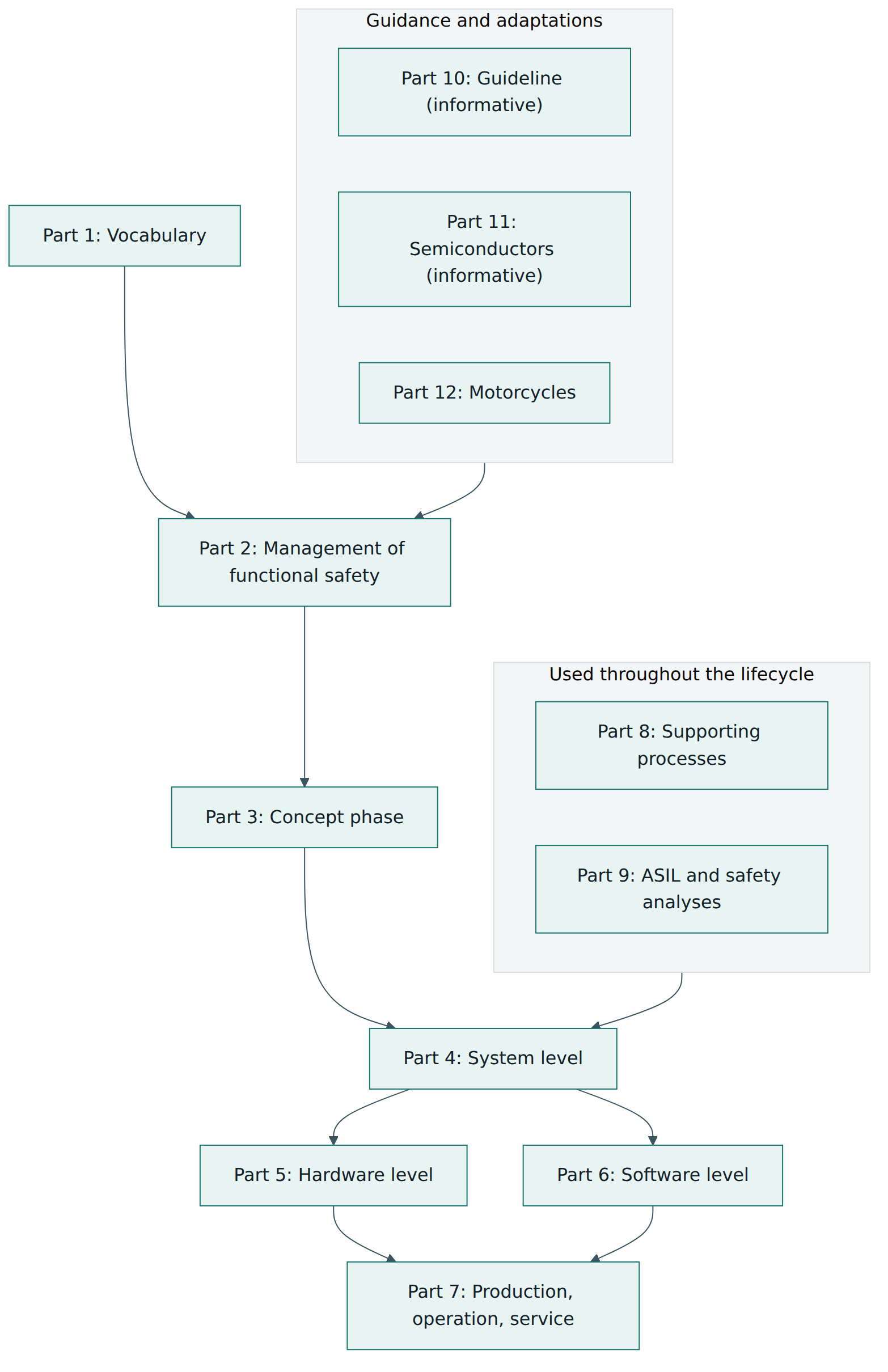
The parts at a glance
| Part | Title (short) | What you use it for |
|---|---|---|
| 1 | Vocabulary | Shared definitions for every other part. |
| 2 | Management of functional safety | Safety culture, competence, quality management, the safety plan, roles, confirmation measures, and the activities after release. |
| 3 | Concept phase | Item definition, HARA, safety goals and the functional safety concept. |
| 4 | Product development at the system level | Technical safety concept, system architecture, hardware-software interface, integration, testing and safety validation. |
| 5 | Product development at the hardware level | Hardware safety requirements and design, the hardware architectural metrics and the evaluation of random hardware failures. |
| 6 | Product development at the software level | Software safety requirements, architecture, unit design and implementation, unit and integration verification, and embedded software testing. |
| 7 | Production, operation, service and decommissioning | Making sure safety is kept in manufacturing, in the field, in repairs and at end of life. |
| 8 | Supporting processes | Distributed development, requirements, configuration and change management, verification, documentation, tool confidence, qualification of components and proven-in-use arguments. |
| 9 | ASIL-oriented and safety-oriented analyses | ASIL decomposition, coexistence of elements with different ASILs, dependent failure analysis and safety analyses such as FMEA and FTA. |
| 10 | Guidelines on ISO 26262 | Informative explanations and examples that help you read the normative parts. |
| 11 | Guidelines on application to semiconductors | Informative guidance for chips and intellectual-property blocks: failure modes, diagnostic coverage, transient faults. |
| 12 | Adaptation for motorcycles | Motorcycle-specific hazard classification (its own integrity levels mapped to ASILs) and adapted requirements. |
How a part is organised
Most normative parts follow a common pattern. Each clause starts with objectives, then lists general information and inputs (the work products from earlier activities that it needs), followed by the requirements and recommendations, and ends with the work products the clause produces. If you are planning a project, the "inputs" and "work products" lists are the easiest way to see what depends on what.
Many requirements are graded by ASIL. They appear as tables of methods, where each method is marked for each ASIL as highly recommended, recommended, or no recommendation for or against. For example, a software verification table might show a structural coverage measure as recommended at ASIL A and highly recommended at ASIL D. You are expected to choose a suitable combination of methods for your ASIL and to justify any highly recommended method you do not use. This is a big difference from a checklist: the standard tells you how much confidence you need and offers proven ways to get it, but the engineering judgement remains yours.
Normative annexes and tailoring
Parts also contain annexes. Each annex is marked as normative (it adds requirements you must apply) or informative (explanations and examples that help you apply the requirements). The standard allows tailoring: you may omit or change an activity if you document a rationale showing that the omission does not compromise safety, and the tailoring is reviewed. Tailoring is also how you apply the standard to a modification of an existing product, where only the changed parts and their impact need full treatment.
Lesson 4 – How it works in practice
ISO 26262 is organised around a safety lifecycle: the sequence of activities from the first idea of a function to its decommissioning. It is closely tied to the V-model used in automotive engineering, in which requirements are refined on the way down (vehicle, system, hardware and software) and verified on the way back up (unit tests, integration, vehicle tests). Figure 2 shows the main flow.
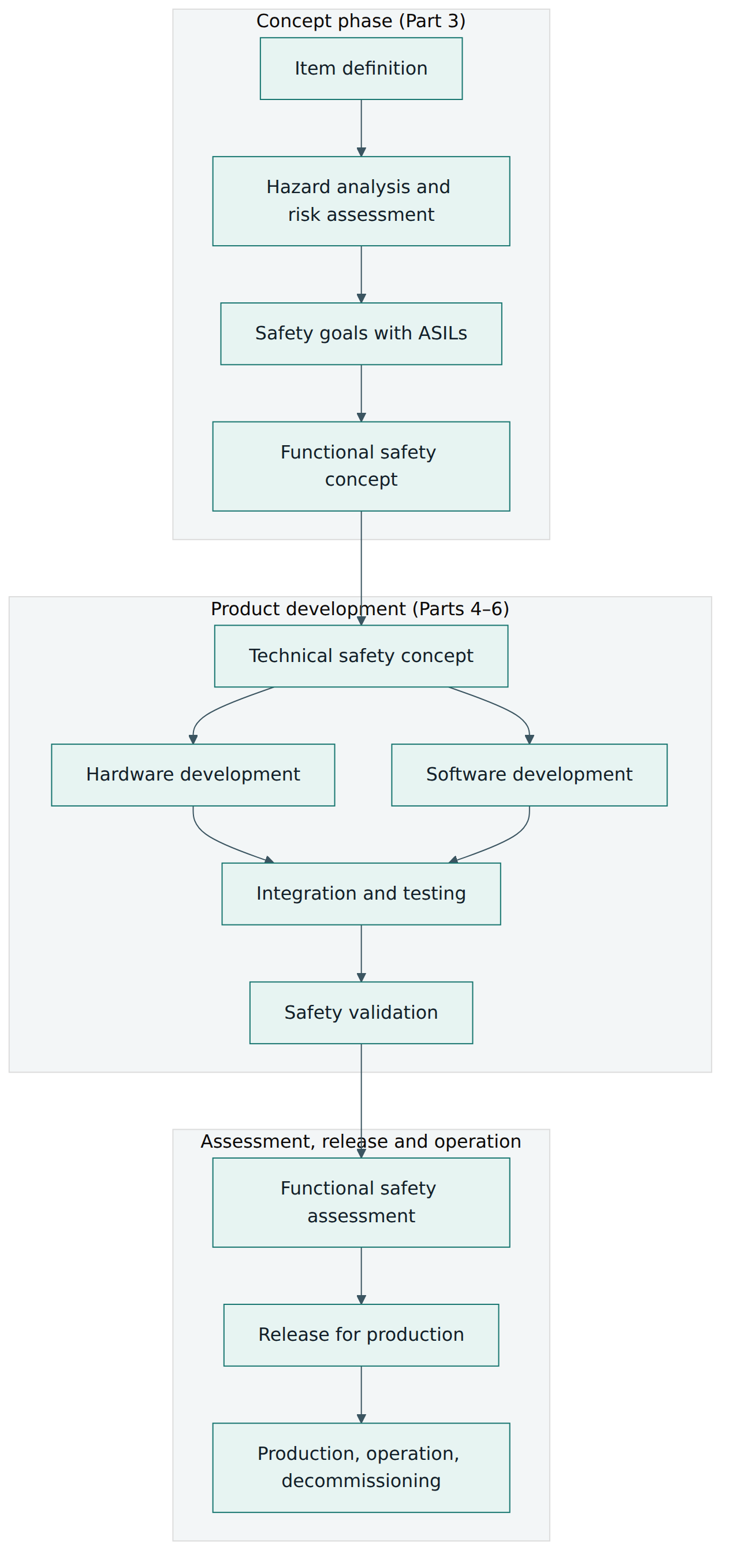
Management of functional safety
Before any engineering, the organisation needs the right foundation (Part 2). At company level this means a safety culture in which safety has priority over cost and schedule and people can raise concerns without fear, rules and processes for functional safety, competence management, a quality management system (commonly IATF 16949 in automotive), and a way to learn from field issues. At project level a safety manager is appointed, a safety plan lists the activities, responsibilities, work products and their timing, and the safety case is planned from the start. If the project modifies an existing item, an impact analysis decides what must be redone.
Concept phase: from item to safety goals
The concept phase begins with the item definition: what the function does, its boundaries, its interfaces with the driver, other vehicle systems and the environment, its operating modes, legal requirements and known hazards from similar products.
Next comes the HARA. The team lists the malfunctioning behaviours of the item at vehicle level (too much, too little, too early, too late, unintended, missing), combines each with relevant operational situations, and rates each hazardous event on three parameters:
- Severity (S0 to S3): how badly people could be hurt, from no injuries (S0) through light and moderate (S1), severe and life-threatening with survival probable (S2), to life-threatening with survival uncertain, or fatal (S3).
- Exposure (E0 to E4): how often the vehicle is in the operational situation, from incredibly unlikely (E0) to high probability (E4). It can be rated by duration (how long the situation lasts) or by frequency (how often it occurs).
- Controllability (C0 to C3): how well the driver or other people involved can avoid the harm, from controllable in general (C0) through simply (C1) and normally controllable (C2) to difficult to control or uncontrollable (C3).
A table in Part 3 combines the three classes into QM or ASIL A to D. If any parameter is 0, no ASIL is assigned. Otherwise a handy memory aid reproduces the table: add the class numbers, and a total of 10 gives ASIL D, 9 gives C, 8 gives B, 7 gives A, and 6 or less gives QM. ASIL D therefore only arises for the worst combination: S3, E4 and C3. Figure 3 shows the logic.
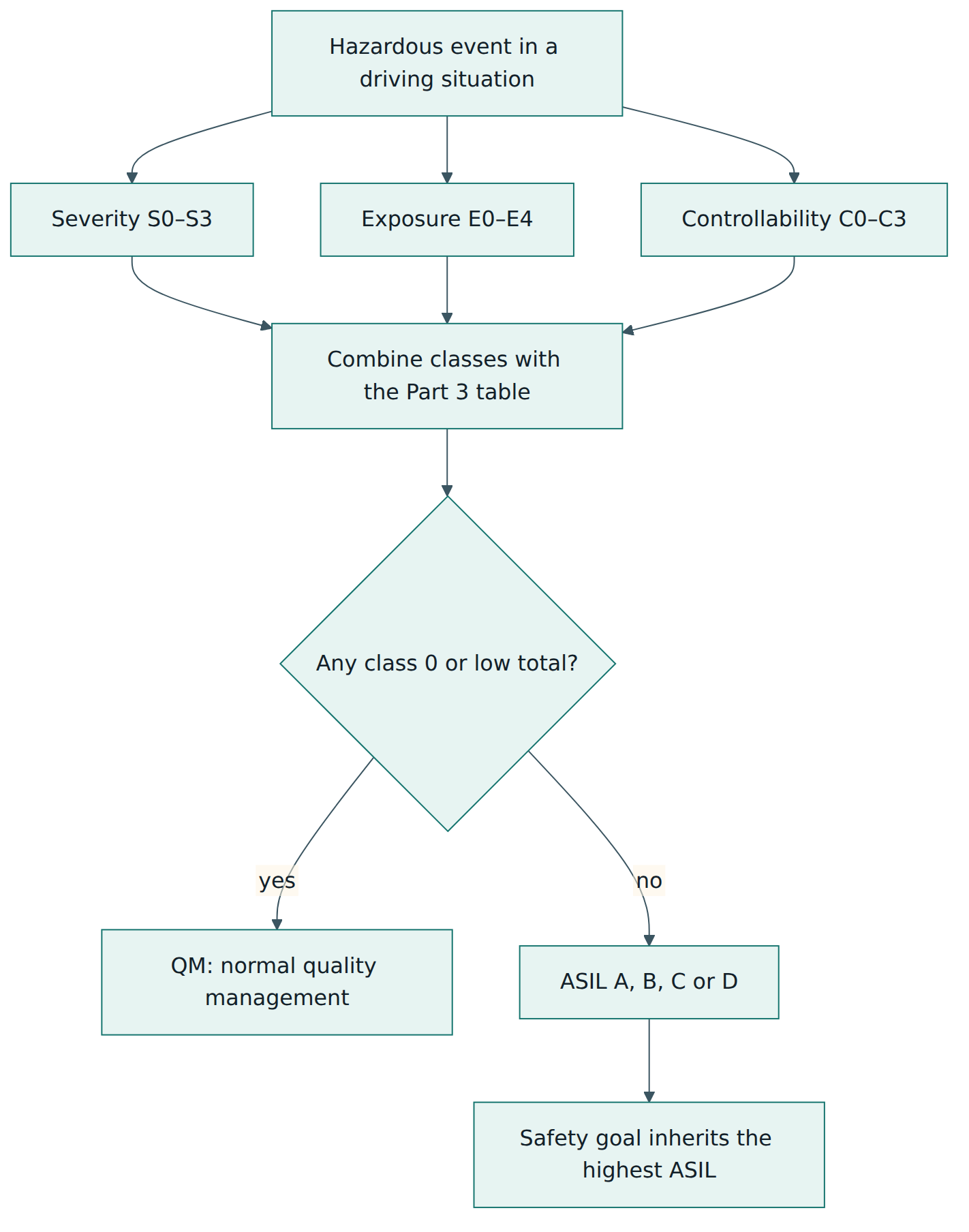
For each hazardous event with an ASIL, the team writes a safety goal at vehicle level, with the ASIL, and where applicable a safe state and the FTTI. Similar safety goals can be merged, keeping the highest ASIL. The functional safety concept then derives functional safety requirements from each safety goal and allocates them to elements of a preliminary architecture: for example "detect a torque sensor failure", "limit the motor torque", "switch to the safe state", "warn the driver".
System level: the technical safety concept
At the system level (Part 4) the functional requirements become technical safety requirements: concrete statements about how the system detects and handles faults, how fast, with what safety mechanisms, and how it reaches and leaves the safe state. The technical safety concept shows the system architecture that implements them and allocates each requirement to hardware or software. The hardware-software interface (HSI) specification records how software uses hardware resources such as memory, timers, analogue inputs and diagnostic features. Figure 4 shows how requirements flow downwards and keep their ASIL unless decomposition is applied.
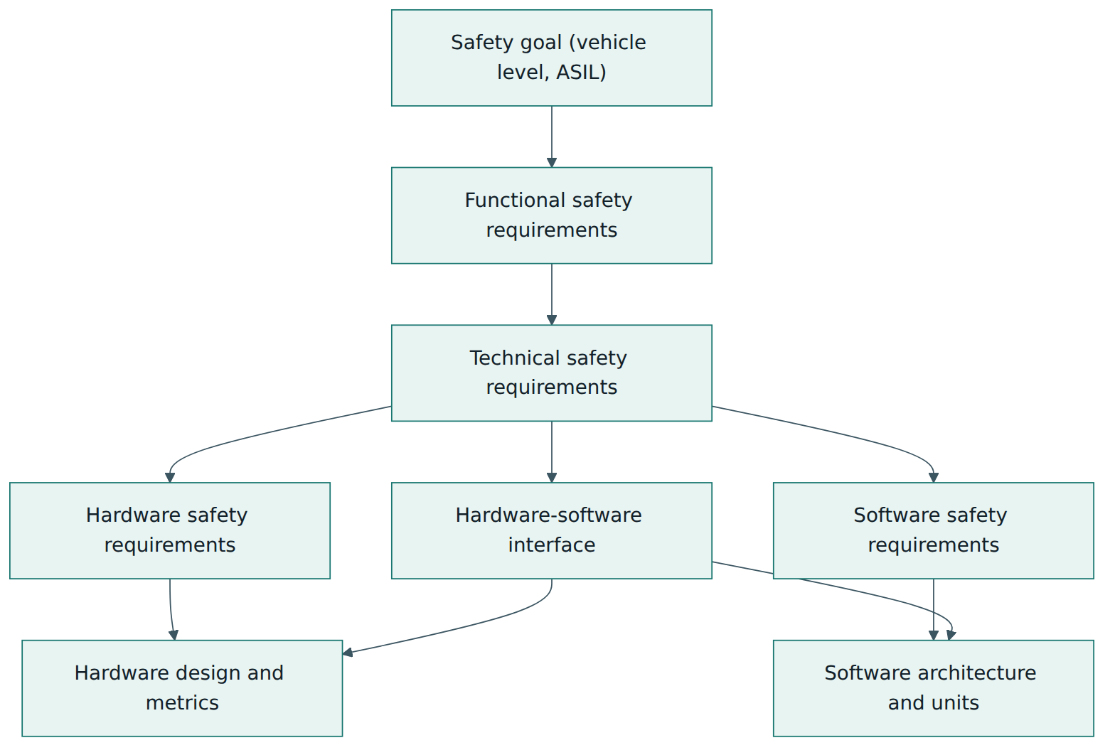
Hardware level
Hardware development (Part 5) adds two things that make automotive functional safety distinctive. First, random hardware failures are analysed quantitatively, typically with an FMEDA (failure modes, effects and diagnostic analysis) that assigns failure rates to each part and its failure modes, and records which safety mechanism covers each mode. Second, the results are compared with target values:
- the single-point fault metric (SPFM) shows how well the design avoids faults that on their own lead directly to violating a safety goal;
- the latent fault metric (LFM) shows how well it avoids hidden multiple-point faults;
- the probabilistic metric for random hardware failures (PMHF) gives an overall residual failure rate per safety goal, usually expressed in FIT (failures in time, one FIT being one failure per billion hours).
The reference targets rise with ASIL. For ASIL D they are commonly quoted as at least 99 % SPFM, at least 90 % LFM and a PMHF below 10 FIT; ASIL B targets are lower (around 90 % SPFM and 60 % LFM). An alternative method evaluates each cause of a possible violation of a safety goal individually. Part 11 explains how these analyses apply inside a microcontroller, including transient faults such as radiation-induced bit flips.
Software level
Software development (Part 6) follows its own small V-model: software safety requirements, software architectural design, unit design and implementation, unit verification, software integration and verification, and testing of the embedded software. Requirements focus on avoiding systematic faults: modelling and coding guidelines (MISRA C is a widely used example), restricted language features, defensive programming, static analysis, reviews, requirements-based testing, fault-injection testing and structural coverage. Coverage expectations rise with ASIL; at ASIL D, modified condition/decision coverage (MC/DC) at unit level is highly recommended. When software parts with different ASILs share a processor, the architecture must show freedom from interference in memory, timing and the exchange of information, for example by using a memory protection unit, timing supervision and end-to-end protection of messages.
Integration, validation and release
Hardware and software are integrated and tested, then the system, then the item in the vehicle (Part 4). Tests check that the safety mechanisms really detect faults within their time budgets, often by injecting faults. Safety validation then gives evidence at vehicle level that the safety goals are met and that the assumptions made in the HARA, such as controllability, hold in reality. After the functional safety assessment, the item is released for production.
Supporting processes
Part 8 supplies the "plumbing" that every project needs. A Development Interface Agreement (DIA) splits safety responsibilities and work products between customer and supplier. Requirements must be unambiguous, verifiable and traceable. Configuration and change management keep the safety case consistent as designs evolve. Every software tool that could introduce or fail to detect errors is classified by tool impact and tool error detection into a tool confidence level (TCL1 to TCL3); tools at TCL2 or TCL3 need qualification, for example through increased confidence from use, evaluation of the tool's development process or validation of the tool. Further clauses cover qualification of software components and hardware elements, and arguments based on proven field experience ("proven in use").
Production, operation and decommissioning
Safety does not end at the factory gate (Part 7 and the post-release clauses of Part 2). Production must preserve the safety-related properties (for example end-of-line tests of safety mechanisms, controlled calibration data), service instructions must not undermine safety, field monitoring must catch safety-related incidents and feed them back into the lifecycle, and decommissioning instructions must be provided where needed. Any software update in the field goes through change management and an impact analysis.
Lesson 5 – Assessment, certification and compliance
Confirmation measures
ISO 26262 builds its own checking into the lifecycle. There are three kinds of confirmation measures, defined in Part 2:
- Confirmation reviews check that key work products, such as the HARA, the safety plan, the safety concepts and the safety case, are complete and technically correct against the standard.
- Functional safety audits check that the processes described in the safety plan are actually being followed.
- The functional safety assessment evaluates whether the functional safety achieved by the item is adequate, considering the work products, the process and the results of the reviews and audits. It ends with a recommendation to accept, conditionally accept or reject.
The standard sets a required independence for each measure, which grows with the ASIL. It uses four levels: I0 (recommended; if it is done, by a person other than the author), I1 (by a person other than the author), I2 (by a person from a different team, not reporting to the same direct superior) and I3 (by a person from a different department or organisation, independent of the release authority in management, resources and release decisions). For the HARA, the review must always be very independent, because a wrong ASIL undermines everything that follows.
The safety case
The safety case brings it all together: a clear argument that the safety goals are achieved, supported by the work products as evidence. Many teams draw it with a graphical notation such as Goal Structuring Notation (GSN), but the standard does not require a specific format. The safety case is reviewed and is a key input to the functional safety assessment and the release decision.
Is there an "ISO 26262 certificate"?
This is one of the most common questions. The honest answer has three parts:
- ISO 26262 is not a management-system standard like ISO 9001, and there is no ISO-defined, accredited certification scheme for it. ISO itself never certifies anyone.
- Commercial assessment bodies (for example the TÜV organisations, exida, UL Solutions, SGS and others) offer certificates for processes (an organisation's development process conforms to the standard), products (a specific element, such as a microcontroller, was developed and assessed for a stated ASIL), tools (a compiler or test tool is suitable for use up to a stated TCL or ASIL) and people (training-based personal qualifications). These are useful evidence, but their meaning depends on the scope written on the certificate.
- What really matters is the functional safety assessment of your item. A certified microcontroller does not make your steering system safe; it gives you a well-documented element whose safety manual and assumptions of use you still have to follow and verify.
Legal and contractual status
In most countries ISO 26262 is not itself a law. It becomes binding in three ways. Carmakers write it into supply contracts and quality agreements, so a supplier who cannot show conformance does not win the business. Courts and product-liability claims judge whether a product reflected the state of the art, and ISO 26262 is widely regarded as the state of the art for automotive functional safety. And vehicle type-approval rules increasingly expect documented safety processes; for example, UNECE regulations for systems such as steering contain an annex on the safety of complex electronic control systems, and manufacturers often use their ISO 26262 work products to answer it. Because organisations apply the standard by agreement, "compliance" usually means "we can show, through assessed work products, that we met the requirements applicable to our role and ASIL".
Lesson 6 – Worked example
This example follows a fictional Tier 1 supplier, SteerWell Systems, developing a column-mounted electric power steering (EPS) system for a new mid-size car from a fictional carmaker. The ratings and numbers are illustrative; real projects derive them from their own analysis and the OEM's rating guidelines.
Step 1 – Organisation and agreements
SteerWell already has a company functional safety process, a quality management system and trained engineers. For this project it appoints a safety manager and signs a DIA with the carmaker: the carmaker owns the item definition and the vehicle-level HARA and safety validation; SteerWell owns the EPS system development, hardware, software and the system-level safety case; the microcontroller vendor supplies its chip as an SEooC with a safety manual. The safety plan lists every work product, its owner, and its confirmation measures with the required independence.
Step 2 – Item definition and HARA
The item is defined as the EPS system: a torque sensor measuring the driver's effort on the steering wheel, an ECU that calculates assist torque using vehicle speed from the vehicle network, and an electric motor driving the column through a gearbox. The mechanical link from steering wheel to wheels stays in place, so the driver can always steer without assist, though with much more effort.
The joint HARA workshop identifies several hazardous events. Two examples:
| Hazardous event | S | E | C | Result |
|---|---|---|---|---|
| H1: unintended steering torque ("self-steering") while driving at high speed on a motorway | S3 | E4 | C3 | ASIL D |
| H2: sudden loss of assist while turning at moderate speed on a country road | S2 | E3 | C2 | ASIL A |
The team documents its reasoning: motorway driving is a common, long-lasting situation (E4); a sudden steering torque at high speed could push the car into oncoming traffic (S3); and most drivers could not correct a strong unexpected pull in time (C3). For H2, the driver can still steer with more effort, so the team judges most drivers able to keep control (C2), an assumption to be checked later in safety validation. The confirmation review of the HARA, done by the carmaker's central safety department (I3), challenges the exposure rating of H2 and accepts it after the team adds data on time spent on such roads.
Step 3 – Safety goals and functional safety concept
From H1 the team writes SG1: avoid unintended steering torque above a defined limit (ASIL D), with the safe state "assist ramped down to zero, driver warned" and an FTTI derived from vehicle dynamics tests (assumed as tens of milliseconds for this example). From H2 comes SG2: avoid sudden loss of assist (ASIL A). The two goals pull in different directions: switching off assist abruptly to satisfy SG1 could violate SG2. The functional safety concept therefore requires the system to detect implausible torque requests quickly and reduce assist gradually where the fault allows, cutting it immediately only when an unintended torque is being produced. Functional safety requirements include: monitor the torque sensor for plausibility, check the calculated assist torque against the driver's input, be able to disable the motor through a path independent of the main software, and inform the driver through a warning lamp.
Step 4 – Technical safety concept and decomposition
The system architecture uses a dual-channel torque sensor (two independent signals compared continuously), a lockstep microcontroller (two cores executing the same code and comparing results), a separate monitoring function that checks the plausibility of the motor torque request, and a motor driver with a hardware disable line controlled by both the monitor and an external watchdog. The team considers decomposing the ASIL D requirement "prevent unintended torque" into ASIL B(D) for the main torque calculation and ASIL B(D) for the independent monitor. That only works if the two are truly independent, so a dependent failure analysis checks shared causes such as a common power supply, common clock, shared memory and the same software compiler. Where shared resources remain, they are developed to ASIL D or covered by additional safety mechanisms.
Step 5 – Hardware and software development
The hardware team runs an FMEDA of the ECU. The first version reaches an SPFM of 97 %, below the ASIL D target, because a single failure of the motor driver's gate supply was not covered. Adding a supply monitor raises it to 99.2 %. A latent fault in the disable path, which is never used in normal operation, is addressed by testing the path at every start-up, lifting the LFM above 90 %. The PMHF for SG1, including the microcontroller vendor's data from its safety manual, stays below the target.
The software team writes software safety requirements and an architecture in which ASIL D monitoring software runs in a protected memory partition, separate from the QM diagnostic and communication code. It applies its coding guideline, static analysis and unit tests with MC/DC coverage for the ASIL D units. The compiler and the unit-test tool are classified: the compiler could introduce errors that later tests might miss, so it reaches TCL3 and SteerWell relies on the vendor's qualification kit and certificate plus its own validation of the features it uses.
Step 6 – Integration, validation and assessment
Hardware-software integration tests inject faults: one torque sensor channel is disconnected, a memory bit is corrupted, the watchdog is starved. Each time, the system must reach the safe state inside the agreed time. The carmaker performs vehicle-level safety validation, including tests with ordinary drivers to confirm that a gradual loss of assist is controllable, which supports the C2 rating of H2. SteerWell compiles its safety case. A functional safety audit finds that change requests in the last sprint skipped the impact analysis; this is corrected before the functional safety assessment, which an assessor from SteerWell's independent corporate safety group carries out. The assessment recommends acceptance with one condition (closing two open test reports), which is tracked to closure before release for production.
Step 7 – Production and field
The production plan includes end-of-line checks of the torque sensor calibration and a functional test of the motor disable path. After launch, the field monitoring process tracks warranty returns and incident reports. When a later software update is planned to improve steering feel, the change goes through impact analysis; because it touches the assist calculation, the affected safety requirements, tests and safety case sections are updated and re-reviewed before the update is released.
Notice how every part of the standard appeared: management (Part 2), concept (Part 3), system, hardware and software (Parts 4–6), production (Part 7), the DIA, tool qualification and change management (Part 8), decomposition and dependent failure analysis (Part 9), and semiconductor guidance (Part 11) for the microcontroller.
Lesson 7 – Relationship to other standards and frameworks
ISO 26262 is one piece of a larger set of standards a vehicle programme uses. Knowing where its boundaries lie prevents gaps and duplicated work. Figure 5 shows the main neighbours.
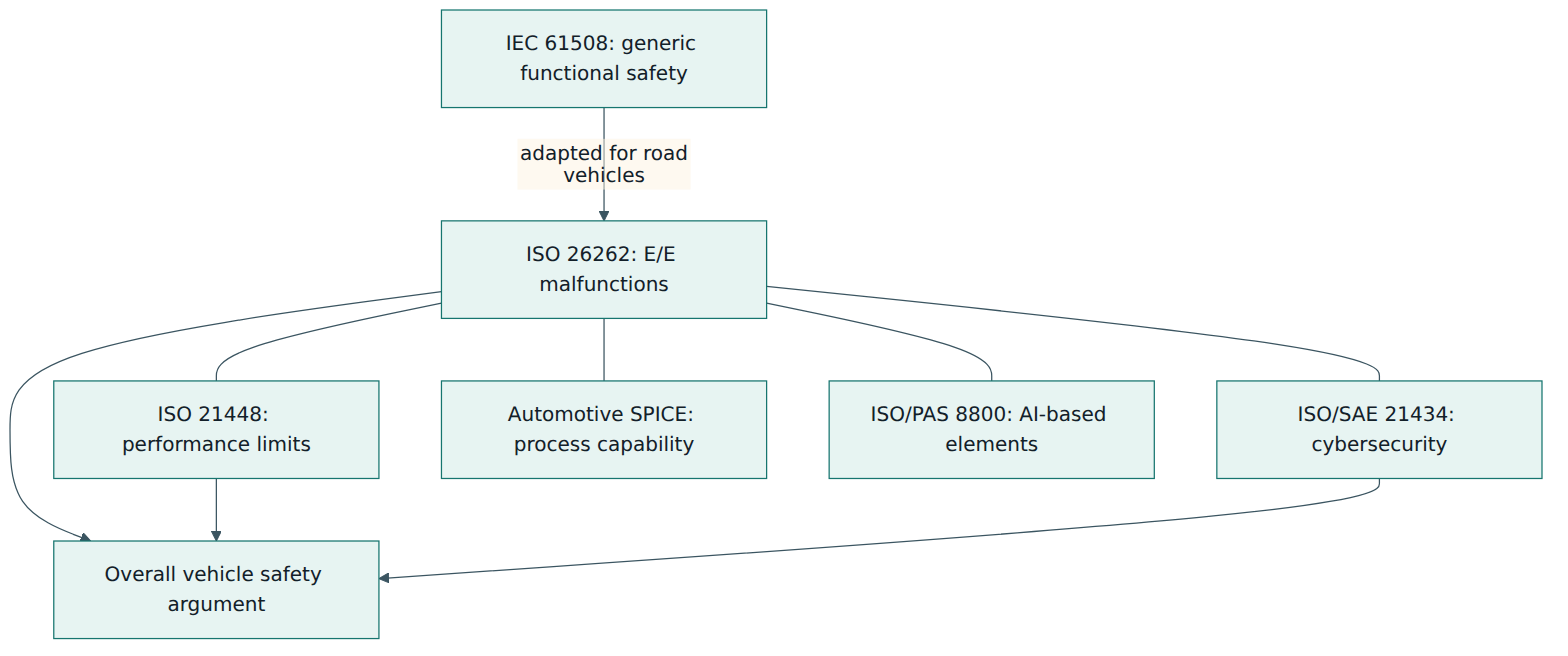
| Standard / framework | Main question it answers | Relationship to ISO 26262 |
|---|---|---|
| IEC 61508 | How to achieve functional safety in electrical, electronic and programmable systems in general | The parent standard. ISO 26262 adapts its ideas for mass-produced road vehicles; ASILs replace IEC 61508's Safety Integrity Levels (SILs), and the two scales are not directly interchangeable. |
| ISO 21448 (SOTIF) | Is the intended function safe when nothing is broken, given sensor and algorithm limits and foreseeable misuse? | Complementary. ISO 26262 covers malfunctions; SOTIF covers functional insufficiencies. Driver-assistance and automated-driving features need both. |
| ISO/SAE 21434 | How to manage cybersecurity risk across the vehicle lifecycle | Complementary. An attack can cause a safety hazard, so the safety and security teams coordinate on shared assets, interfaces and analyses. |
| Automotive SPICE | How capable are the development processes (requirements, design, testing, management)? | Complementary. A capable engineering process is a strong base for avoiding systematic faults; ASPICE assessments do not assess functional safety itself. |
| IATF 16949 | Is there a robust automotive quality management system? | A prerequisite in practice: ISO 26262 expects a quality management system and builds functional safety on top of it. |
| ISO/PAS 8800 | How to address safety of AI and machine-learning elements in road vehicles | Extends the ISO 26262 and SOTIF way of thinking to AI components, such as data and training. |
Interfaces that need attention
Three interfaces deserve special care. First, with SOTIF: the same hazard list can feed both analyses, but the causes differ, and each needs its own measures. Second, with cybersecurity: ISO 26262:2018 asks for communication channels between the safety and security activities, for example so that a security measure such as a message authentication check does not create a new safety problem through extra latency. Third, with process frameworks: an organisation that runs ASPICE and ISO 26262 separately often produces two sets of plans and reviews; mapping them once saves a lot of effort.
Looking ahead
The third edition under development is expected, according to industry commentary, to address topics such as machine learning, fail-operational architectures (systems that must keep working rather than shut down, as needed for automated driving), safety mechanisms based on predictive maintenance, updated software development requirements and closer consideration of SOTIF. Until it is published, those points are expectations, not requirements. The concepts in this course, from HARA and ASILs to the lifecycle and confirmation measures, are stable foundations that the next edition builds on.
Common pitfalls and best practices
Common pitfalls
- Writing the safety documents after the design is finished. The safety case then describes a design that was never shaped by the analysis, and gaps are found too late to fix cheaply.
- Optimistic HARA ratings. Lowering exposure or controllability to avoid a high ASIL without data creates a weak foundation that reviewers and courts will question.
- Decomposing an ASIL without real independence. Two "independent" channels sharing a power supply, a clock or the same software can fail together; decomposition then gives false comfort.
- Ignoring latent faults. Safety mechanisms that are never tested (a disable path, a redundant sensor) can fail silently and leave the system unprotected when they are finally needed.
- Trusting a certificate blindly. Using a certified chip or tool without reading its safety manual and checking its assumptions of use breaks the chain of evidence.
- Skipping impact analysis for "small" changes. A minor calibration or software update can invalidate tests and analyses that the safety case depends on.
- Confusing the scopes of neighbouring standards. Expecting ISO 26262 to cover sensor performance limits or attacks leaves SOTIF and cybersecurity gaps.
Best practices
- Start safety work at the concept stage, with a named safety manager and a safety plan agreed before design decisions are locked.
- Base HARA ratings on evidence – driving data, accident statistics, controllability studies – and keep the rationale for every rating.
- Keep bidirectional traceability from safety goals down to hardware and software requirements, tests and results, ideally in a requirements tool.
- Agree the DIA early with customers and suppliers so that everyone knows which work products they owe and receive.
- Run a dependent failure analysis whenever you rely on redundancy or on mixing ASILs on one platform.
- Plan confirmation measures with the right independence into the schedule, rather than bolting them on before release.
- Build a real safety culture: reward people who raise safety concerns, train teams regularly and learn from field data.
Summary and key takeaways
- ISO 26262 is the functional safety standard for series-production road vehicles; it targets the absence of unreasonable risk from malfunctioning E/E systems.
- The current edition is ISO 26262:2018 (12 parts); a third edition is at draft (DIS) stage and not yet published.
- Risk is rated for hazardous events by severity, exposure and controllability, giving QM or ASIL A to D; the ASIL sets the rigour of everything that follows.
- Safety goals are refined into functional, technical, hardware and software safety requirements, with traceability and verification at every level.
- Random hardware failures are handled with quantitative metrics (SPFM, LFM, PMHF); systematic failures are handled with disciplined processes, methods and tools.
- Confirmation reviews, audits and the functional safety assessment, with independence rising by ASIL, check the work; the safety case brings the argument together.
- There is no ISO certification for ISO 26262; third-party certificates help, but your item's own assessed safety case is what counts.
- ISO 26262 works alongside ISO 21448, ISO/SAE 21434, Automotive SPICE and quality management standards; each covers a different question.
Reflection questions
- Pick a vehicle function you know (for example automatic headlights, an electric parking brake or a battery charger). What would the item definition include, and what are two hazardous events you would rate in its HARA?
- In the EPS example, the two safety goals pulled in opposite directions. Find a similar conflict in a system you know and describe how a safe state could balance it.
- Your team wants to decompose an ASIL D requirement into two ASIL B(D) channels. Which shared resources in your product would you examine first, and why?
- A supplier offers a component "certified to ASIL D". What questions would you ask, and which documents would you want to see, before relying on it?
- Where in your organisation do functional safety, cybersecurity and SOTIF work meet today, and what would you change so that their analyses inform each other?
Further reading and official sources
- ISO 26262-1:2018 Road vehicles – Functional safety – Part 1: Vocabulary – ISO
- ISO 26262-1 next edition (project under development) – ISO
- ISO 26262-11:2018 Guidelines on application of ISO 26262 to semiconductors – ISO
- Assessment of Safety Standards for Automotive Electronic Control Systems – U.S. National Highway Traffic Safety Administration
- Functional safety assessment of a generic steer-by-wire system (report DOT HS 812 576) – U.S. National Highway Traffic Safety Administration
- What to Expect with Version 3 of ISO 26262 – UL Solutions
Original tutorial by xOps School (DevOpsSchool Private Limited), written from public sources about ISO 26262. Not affiliated with or endorsed by the standard's owner; standard names are trademarks of their owners. Buy the official standard from its publisher for the authoritative text.