
DO-254 – Tutorial (about 60 minutes)
- View
DO-254 is the aviation industry's guidance for showing that airborne electronic hardware, such as an FPGA (field programmable gate array) or a custom chip inside a flight computer, was developed carefully enough that design errors are unlikely to make the aircraft unsafe. Avionics companies, their chip and board designers, verification engineers and certification specialists use it to earn approval from aviation authorities such as the FAA (Federal Aviation Administration, United States) and EASA (European Union Aviation Safety Agency). After this tutorial you will be able to explain why the guidance exists, describe its life cycle and its design assurance levels, read a hardware certification plan with understanding, and outline how a real FPGA project would show compliance.
Course overview
Edition and status: the current and only edition is RTCA DO-254, Design Assurance Guidance for Airborne Electronic Hardware, published by RTCA, Inc. on 19 April 2000. It was prepared jointly by RTCA Special Committee SC-180 and EUROCAE Working Group WG-46, and Europe publishes the identical text as EUROCAE ED-80 (April 2000); authorities treat the two as equivalent. DO-254 itself has never been revised. Instead, regulators add clarifications on top of it: the FAA through Advisory Circular AC 20-152A (dated 7 October 2022, which cancelled the original AC 20-152 of 2005), the companion best-practice circular AC 00-72 (also 7 October 2022) and FAA Order 8110.105B (effective 20 February 2024, guidance for FAA staff); EASA through AMC 20-152A (adopted by ED Decision 2020/010/R in 2020). A revision is being prepared: RTCA set up SC-243, Airborne Electronic Hardware Development Assurance, in 2024 to work jointly with EUROCAE WG-128, first on a report that establishes the need and scope for an update; its terms of reference were approved in March 2026. No revised edition (a future "DO-254A") has been published, so this course teaches DO-254 (2000) as applied through AC 20-152A and AMC 20-152A. Verified 2026-10-29 against the FAA's published AC 20-152A, AC 00-72 and Order 8110.105B, the EASA announcement of AMC 20-152A, and RTCA's SC-243 committee page.
Who it is for: digital and board-level hardware engineers, FPGA and ASIC designers, verification engineers, quality and process assurance staff, project managers and certification engineers who are new to airborne hardware certification. It also suits software people who know DO-178C and want to understand the hardware side, and engineers from automotive or industrial safety who are moving into aerospace.
Prerequisites: none. A rough idea of what an FPGA is (a chip whose logic you configure with a design written in a hardware description language) helps, but every technical term is explained the first time it appears.
By the end of this tutorial:
- You will be able to explain why aviation needs design assurance for electronic hardware and what problem DO-254 solves that testing alone cannot.
- You will be able to define the core vocabulary: design assurance level, hardware item, simple and complex hardware, derived requirement, validation, verification, independence and hardware control category.
- You will be able to describe the structure of DO-254: its planning, design and supporting processes, its life cycle data and its appendices.
- You will be able to explain how the design assurance level changes the amount of work, including the extra methods required for the two highest levels.
- You will be able to describe how authorities review and accept a DO-254 project, and why there is no stand-alone "DO-254 certificate".
- You will be able to plan the main steps of a realistic FPGA project, including tools, commercial intellectual property and the final compliance summary.
- You will be able to place DO-254 among its neighbours: ARP4754B, ARP4761A, DO-178C, AC 20-152A and similar standards in other industries.
Lesson 1 – Origins, purpose and scope
Why hardware needs "design assurance"
Aircraft have depended on electronics for decades, but in the 1990s something changed. Functions that used to be built from many small, simple parts started to be packed into single devices with hundreds of thousands, and later millions, of logic gates: programmable logic devices (PLDs), FPGAs and application specific integrated circuits (ASICs). These devices behave much more like software than like a resistor or a relay. Their behaviour comes from a design written in a hardware description language (HDL) such as VHDL or Verilog, they contain state machines with many possible states, and they can hide a design error that only appears under a rare combination of inputs and timing.
Traditional hardware qualification focused on physical failures: does the part survive vibration, temperature and lightning, and how often does it wear out? Those questions are about random failures, which can be estimated with reliability numbers. A design error is different. It is systematic: every unit built from the same design contains it, it does not show up in a reliability calculation, and exhaustive testing of a complex device is impossible because the number of input and state combinations is astronomically large. The only practical defence is to make the development process itself disciplined enough that errors are prevented or caught early. That discipline is what aviation calls design assurance (newer FAA and EASA documents say development assurance; the idea is the same).
The software world met the same problem earlier and answered it with DO-178 (now DO-178C). Hardware had no equivalent, so RTCA and EUROCAE, two non-profit bodies that write consensus guidance for aviation, formed a joint committee to create one. The result, published in April 2000, was DO-254 in the United States and ED-80 in Europe.
What DO-254 is, and what it is not
DO-254 is guidance, not law. Aviation regulations require that equipment performs its intended function and that failures are acceptably unlikely given their severity, but they do not say how to develop an FPGA. An authority can recognise a document like DO-254 as an acceptable means (not the only means) of showing that the regulations are met. Once an applicant chooses that route, the authority expects the applicant to follow it fully, or to agree any deviations in advance.
DO-254 is also process-oriented and objective-based. It describes processes (planning, requirements capture, design, verification and so on), states the objectives each process should achieve, and lists the data that shows the objectives were met. It does not prescribe a design method, a tool or a coding style. A team can use any HDL, simulator or document template as long as the objectives are satisfied and the evidence exists.
Finally, DO-254 is about design errors, not about physical robustness. Environmental testing of equipment (temperature, vibration, lightning, electromagnetic interference) is covered by a different RTCA document, DO-160, and reliability analysis belongs to the safety assessment. DO-254 makes sure the design does what was intended; other activities make sure the physical product survives its environment.
Scope: written broadly, applied selectively
The text of DO-254 was written so that it could apply to almost any airborne electronic hardware: line replaceable units (the boxes installed on an aircraft), circuit board assemblies, custom micro-coded components such as PLDs, FPGAs and ASICs, integrated technology such as hybrids and multi-chip modules, and commercial off-the-shelf (COTS) components. Regulators, however, decide where they actually expect it to be used.
When the FAA first recognised DO-254 in 2005 (AC 20-152), it applied the guidance only to complex custom micro-coded components (PLDs, FPGAs and ASICs) at the three highest design assurance levels. For years that made "DO-254" almost a synonym for "FPGA certification". The 2022 AC 20-152A, harmonised with EASA's AMC 20-152A, broadened the expectations. It still applies to hardware contributing to levels A, B and C, but it now addresses four topics, each with its own numbered objectives: custom device development, COTS intellectual property inside custom devices, the use of COTS devices such as complex processors, and the development of circuit board assemblies. In total it adds 28 objectives (identified with the prefixes CD, IP, COTS and CBA) that supplement or clarify DO-254. For level D hardware, AC 20-152A says its use is not required, and AC 00-72 offers best practices instead.
So when people say "we are doing DO-254", they nearly always mean "we are following DO-254 as clarified by AC 20-152A and AMC 20-152A for this project". Keep that pairing in mind throughout the course.
Lesson 2 – Key concepts and vocabulary
DO-254 uses ordinary words with precise meanings. The terms below appear in every plan, review and audit. The definitions are explanations in plain language, not the official glossary text.
- Airborne electronic hardware (AEH) – any electronic hardware item installed in airborne systems and equipment, from a single chip to a complete circuit board assembly.
- Hardware item – the unit of hardware under consideration in a DO-254 project: a device, a board or a whole assembly. Requirements are allocated to it and it is verified against them.
- Design assurance level (DAL) – a letter from A to E that expresses how much rigour the development needs, based on the worst effect a hardware design error could have on the aircraft. A is the most demanding; E has no DO-254 objectives.
- Failure condition – an effect on the aircraft and its occupants caused by one or more failures or errors, classified by severity (catastrophic, hazardous, major, minor or no safety effect) during the system safety assessment.
- Simple hardware item – an item whose correct behaviour under all foreseeable operating conditions can be shown by a comprehensive combination of deterministic tests and analyses, with no anomalous behaviour. Simple items still need a defined process, but the documentation can be much lighter.
- Complex hardware item – any item that cannot be shown to be simple. Note that a design built entirely from simple pieces can still be complex as a whole.
- Derived requirement – a requirement that comes from a design decision rather than directly from a higher-level requirement, such as the behaviour of a state machine after an illegal state. Derived requirements must be fed back to the system and safety processes so they can check that nothing unsafe was introduced.
- Validation – confirming that the requirements themselves are correct and complete (are we building the right thing?). DO-254 itself concentrates on derived requirements; AC 20-152A expects every custom device requirement to be validated, with independence at levels A and B.
- Verification – confirming that the implemented hardware meets its requirements (did we build it right?), by reviews, analyses and tests.
- Independence – separation of responsibilities so that the person or tool checking an item is not the one who produced it. DO-254 expects independent verification for levels A and B.
- Traceability – documented links in both directions between requirements, design, verification cases and results, so every requirement is implemented and verified and nothing unexplained is in the design.
- Hardware control category (HC1 / HC2) – the strength of configuration management applied to a life cycle data item. HC1 means full control, including problem reporting and formal change control; HC2 is a reduced set (identification, protection, retrieval and basic change control).
- PHAC (Plan for Hardware Aspects of Certification) – the top-level plan that tells the authority what the hardware is, its DAL, the processes and tools that will be used and how each objective will be met.
- HAS (Hardware Accomplishment Summary) – the closing document that states how the PHAC was carried out, lists deviations and open problems, and declares compliance.
- COTS IP – commercially available design blocks (for example an Ethernet or memory controller) supplied as HDL code (soft IP), as a technology-specific netlist (firm IP) or as a physical layout (hard IP), and integrated into a custom device.
Design assurance levels and failure conditions
The DAL is not chosen by the hardware team. It flows down from the aircraft and system safety assessment, which looks at each function, imagines how it could fail or misbehave and classifies the worst credible effect. The hardware that implements a function inherits the level matching that classification. A catastrophic failure condition (one that would prevent continued safe flight and landing) leads to level A; hazardous (severe-major in older European wording) to level B; major to level C; minor to level D; and no safety effect to level E.
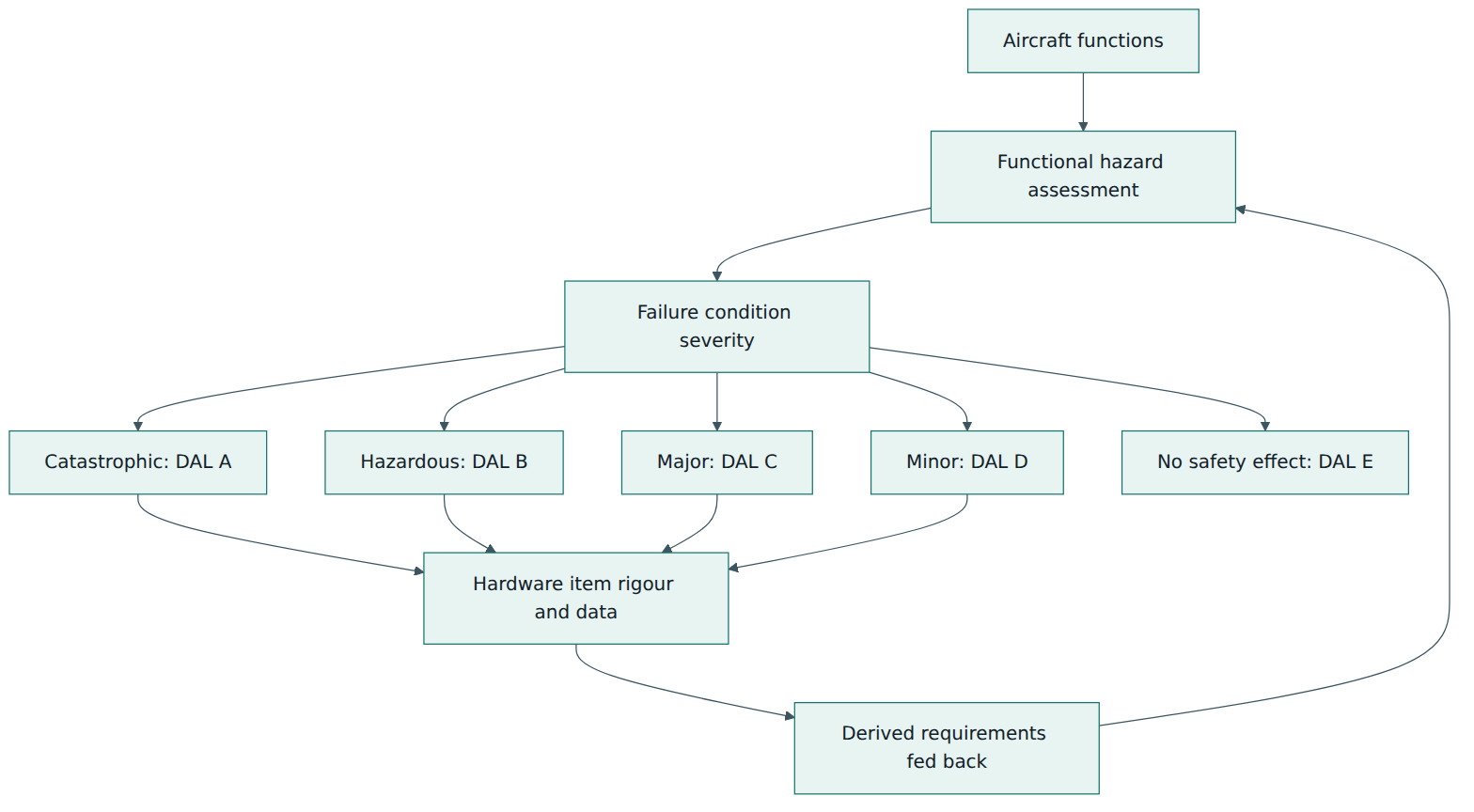
Two points about Figure 1 are worth stressing. First, architecture can change the level: if a system uses two dissimilar, independent channels, the safety assessment may allow each channel's hardware to be developed at a lower level than a single channel would need. That decision belongs to the system process (ARP4754B) and must be justified there, not assumed by the hardware team. Second, the arrow back from the hardware to the safety process is not decoration. Derived requirements, unused functions and design limitations discovered during hardware work can create new failure modes, and the safety assessment must see them.
Lesson 3 – Structure of DO-254
DO-254 is a document of eleven sections and four appendices. You do not need to memorise numbers, but knowing the layout helps you navigate plans, review checklists and authority comments, which often cite sections directly.
The main sections
- Section 1 – Introduction: purpose, scope, the kinds of hardware covered, and how complexity affects the approach.
- Section 2 – System aspects of hardware design assurance: how the hardware process connects to the system development and safety assessment, how requirements and DALs are allocated, and what information flows back.
- Section 3 – Hardware design life cycle: the idea that a project chooses its own life cycle (waterfall, iterative, incremental) as long as the processes, their transition criteria and their data are defined.
- Section 4 – Planning process: producing the plans and standards and agreeing them before the main work starts.
- Section 5 – Hardware design processes: requirements capture, conceptual design, detailed design, implementation and production transition.
- Section 6 – Validation and verification process: validating derived requirements, verifying the design and implementation, and the methods available (reviews, analyses, tests) including coverage analysis.
- Section 7 – Configuration management process: identifying items and baselines, problem reporting, change control, release, retrieval and protection.
- Section 8 – Process assurance: confirming that the project actually follows its plans and standards, and that deviations are detected and resolved.
- Section 9 – Certification liaison process: communication with the certification authority, from the PHAC to the final summary.
- Section 10 – Hardware design life cycle data: a description of each data item: plans, standards, design data, verification data, records and the accomplishment summary.
- Section 11 – Additional considerations: previously developed hardware, COTS components, product service experience, and tool assessment and qualification.
The appendices
Appendix A modulates the life cycle data by DAL. It is a table that lists each data item, says whether it must be submitted to the authority, and assigns the hardware control category (HC1 or HC2) per level. AC 20-152A corrects a few entries; for example, it states that detailed design data should be under HC1 for levels A, B and C, and it clarifies that the "top-level drawing" corresponds to a hardware configuration index that identifies the hardware, its embedded logic and its life cycle data.
Appendix B adds design assurance considerations for level A and B functions. Because requirements-based verification alone may miss errors in very critical hardware, the applicant must choose one or more additional methods: architectural mitigation (a design architecture that contains or detects the effect of a design error, such as dissimilar redundancy or monitors), product service experience (credible, relevant in-service history of the same design), or advanced verification methods. The advanced methods are elemental analysis (checking that every design element has been exercised by requirements-based verification), safety-specific analysis (focusing extra scrutiny on the parts of the design that can contribute to the critical failure conditions) and formal methods (mathematical proof of properties). AC 20-152A recognises HDL code coverage, measured during requirements-based simulation, as a way to perform elemental analysis for digital devices.
Appendix C is the glossary and Appendix D lists acronyms.
Processes and their relationships
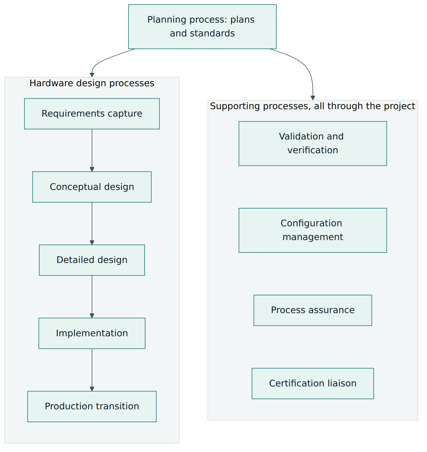
The heart of DO-254 is a set of processes. The planning process comes first. The design processes produce the hardware. The supporting processes run throughout the project and touch every design step. Figure 2 shows this structure.
The five design processes in plain words
Requirements capture turns the requirements allocated from the system into hardware requirements that are clear, verifiable and complete, including timing, interfaces, power-up behaviour, and how the item responds to abnormal inputs. Conceptual design produces a high-level architecture: the main blocks, the clocking scheme, the interfaces and the choice of device. It is where you can still change direction cheaply, and a review at this stage checks consistency with the requirements. Detailed design produces the data needed to build the item: for an FPGA, the HDL code, the timing and pin constraints and the hardware-software interface description. Implementation turns detailed design data into a physical item; for an FPGA this is synthesis, place and route and programming the device, and for a board it is manufacturing a prototype. Production transition makes sure that everything needed to build the item repeatably in series production is captured and controlled, such as the programming file, its checksum and the manufacturing instructions.
The supporting processes in plain words
Validation and verification checks the requirements and the product. Configuration management makes sure you always know exactly which version of each item and data item you have, and that changes are controlled. Process assurance is the project's internal auditor: it is independent of the engineers and confirms that plans are followed. Certification liaison keeps the authority informed and gets its agreement at key points. None of these is a phase; all of them run from planning until the hardware is approved and beyond.
Lesson 4 – How it works in practice
Knowing the structure is one thing; running a project is another. This lesson follows the typical flow of a DO-254 project and the artefacts that each step creates.
Step 1: plans and standards
Planning produces a set of documents that the authority can review before most of the engineering is done. The PHAC is the main one and is submitted to the authority. Supporting plans usually include a hardware design plan, a validation plan, a verification plan, a configuration management plan and a process assurance plan. Some companies combine these; what matters is that each topic is covered. Standards explain how the team will work: a requirements standard (how to write and structure requirements), a hardware design standard that includes the HDL coding rules, a validation and verification standard, and an archive standard for long-term storage. A typical PHAC states the DAL of each device, whether each device is classified simple or complex and why, the life cycle, the tools and their assessment, the use of COTS IP and devices, the Appendix B method for levels A and B, and how the project will satisfy every applicable objective of DO-254 and AC 20-152A.
Planning is also where transition criteria are defined: what must be true before an activity can start or end. For instance, detailed design might not start until the requirements have passed review and are under configuration control. Transition criteria let process assurance check that the project is not skipping steps.
Step 2: requirements and validation
Good hardware requirements are the foundation of everything else, because verification is requirements-based: tests and analyses demonstrate requirements, and coverage is measured against them. Hardware requirements should describe externally observable behaviour, including normal operation, power-up and reset, boundary and abnormal conditions, and timing. AC 20-152A expects that, for levels A and B, abnormal and boundary conditions and the expected response to them are written down as requirements. This is how the robustness of the design is made verifiable.
DO-254's validation process was written mainly for derived requirements, but AC 20-152A asks for all custom device requirements to be validated, because requirements refined or restated at device level can also be wrong; at levels A and B this validation is done with independence. Derived requirements get extra attention: each one is reviewed for correctness and completeness, and passed to the system and safety teams, who decide whether it affects safety. A requirement such as "after detecting an illegal state the controller returns to the idle state within two clock cycles" may look harmless to the designer but matter a lot to the safety engineer.
Step 3: design and implementation, with reviews
Design proceeds through the conceptual and detailed stages with reviews at each. A detailed design review checks the HDL against the design standards and traces the code back to the requirements so there is no unexplained logic. When tools turn the design into a physical implementation, AC 20-152A expects the team to review the tool reports, such as synthesis and place-and-route reports, to make sure the tool ran correctly, for example that no unexpected logic was removed or added and that warnings are understood.
Step 4: verification
Verification is usually the largest part of the effort. For an FPGA it combines several activities:
- Requirements-based simulation of the HDL in a testbench, which can exercise conditions that are hard to create on a board.
- Hardware testing of the programmed device in its intended environment or a representative board. DO-254 favours testing the real item; simulation alone is not enough to show the physical implementation behaves correctly.
- Post-layout simulation using the netlist produced after place and route, when some requirements cannot be reached from the device pins.
- Timing verification that covers temperature, voltage and manufacturing process variation, typically by static timing analysis, as AC 20-152A expects.
- Reviews and analyses, including review of each test case and procedure to confirm it suits the requirement it traces to and that the requirements are fully covered.
- Coverage analysis to show that every requirement has been verified, and for levels A and B the Appendix B method chosen, often elemental analysis through HDL code coverage.
Independence matters here. At levels A and B the verification of an item must be done or reviewed by someone other than its author. A tool can provide independence too, if its output is trusted for that purpose.
Step 5: configuration management and process assurance
From the first plan onward, every data item is identified and placed under the control category that Appendix A assigns. Baselines are taken at agreed points, problem reports record every defect and its resolution, and changes go through a defined change control process. Process assurance audits the project against its plans, witnesses some tests, takes part in the conformity review that checks the final item and data are consistent, and records its findings.
Step 6: tools
Hardware development relies on tools: synthesis and place-and-route tools create the implementation (design tools); simulators and coverage analysers check it (verification tools). A design tool can insert an error into the hardware; a verification tool can fail to detect one. DO-254 therefore asks for a tool assessment, illustrated by a decision flow in Section 11.4. Figure 3 is a simplified paraphrase of that logic.
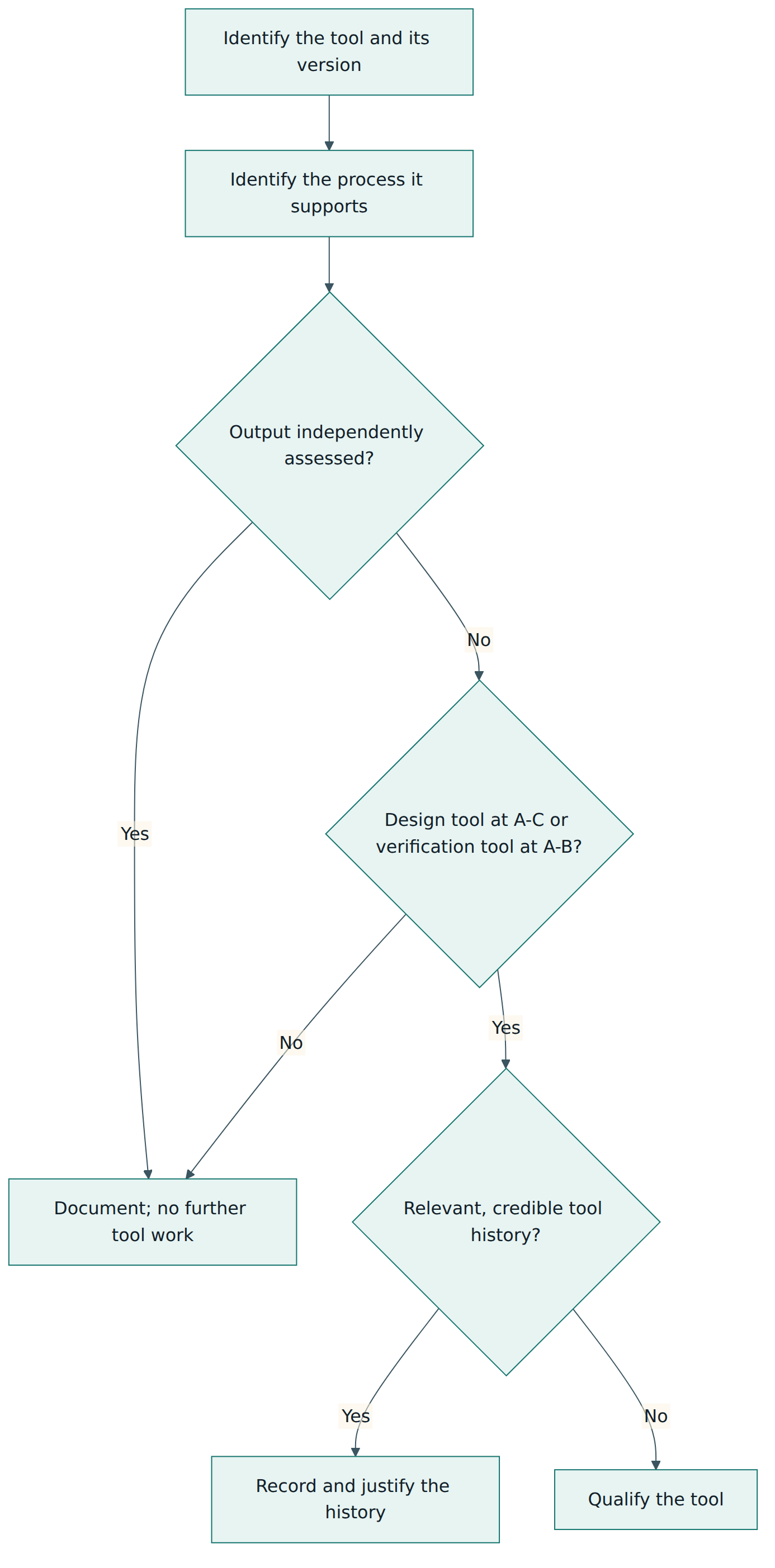
In practice, most projects avoid formal tool qualification by assessing the tool's output independently. For example, the output of synthesis and place and route is covered when the programmed device is fully verified by hardware tests and post-layout analysis against its requirements. AC 20-152A adds important clarifications: the independent assessment must really cover the errors the tool could introduce or miss; any claim of tool history must be backed by data showing it is relevant and credible; and, for design tools, history alone should not be the only basis for trusting the tool.
Step 7: COTS IP and COTS devices
Modern FPGAs often include purchased IP blocks, and boards include complex COTS processors. Neither was developed with DO-254 in mind. AC 20-152A asks the applicant to assess the IP provider and the available data, choose a verification strategy for the IP, capture requirements for the functions used (including configuration and the deactivation of unused functions), and, at levels A and B, satisfy Appendix B for the IP, often using safety-specific analysis where code coverage is not possible. For complex COTS devices it asks for a component management process, review of the device errata (known defects published by the manufacturer) with verified mitigations, and a clear definition of how the device is used.
Lesson 5 – Assessment, certification and compliance
There is no stand-alone DO-254 certificate
A frequent misunderstanding is that a company or a chip can be "DO-254 certified" in the way a company is certified to ISO 9001. That is not how aviation works. Aviation authorities approve aircraft, engines, propellers and certain articles, through a type certificate (TC), a supplemental type certificate (STC) for a modification, or a technical standard order authorisation (TSOA) for equipment built to a minimum performance standard. DO-254 compliance is one part of the evidence for such an approval, assessed for a specific hardware item, in a specific installation, at a specific DAL. A device approved in one aircraft is not automatically approved in another: the new applicant must show that the earlier evidence still holds for the new use, which DO-254 handles under previously developed hardware.
Training providers and tool vendors may issue certificates of attendance or "DO-254 ready" claims for IP blocks and tools. These can be useful inputs, but they do not replace the applicant's own compliance for the actual project. An IP vendor's data package may make compliance easier; it does not make the hardware approved.
Who assesses, and how
The certification authority (for example the FAA in the United States or EASA in Europe) has the final say. Much of the review work is delegated to approved individuals or organisations; in the United States these include designated engineering representatives (DERs) and organisation designation authorisation (ODA) units. FAA Order 8110.105B explains how FAA staff use DO-254 and AC 20-152A on projects. It describes on-site and desk reviews of hardware processes and data, and offers example worksheets to set the authority's level of involvement: medium or high for levels A and B, low or medium for level C and low for level D, refined by factors such as the applicant's experience, its track record and its use of complex COTS devices or COTS IP.
Many programmes organise authority reviews around four "stages of involvement", a convention from earlier FAA guidance that industry still uses widely: a planning review (are the plans and standards complete and compliant?), a design review (is the design being produced according to plan, with traceability?), a verification review (are verification cases, procedures and results complete and correct?) and a final review (is the item ready for approval, with all data complete and problem reports resolved?). The exact number and timing of reviews is agreed with the authority for each project.
Evidence and closure
Compliance is shown through life cycle data. The PHAC and the HAS are always submitted. Other items, such as the hardware configuration index, the verification results and the problem reports, are submitted or made available depending on the level and the authority's request. The HAS states what was done, lists any deviation from the plans, and identifies open problem reports with a justification of why they are acceptable. In practice, authorities expect open problem reports at approval to be few, well understood and shown to have no safety impact; EASA has also published guidance on managing open problem reports.
How the level changes the work
The DAL scales the effort in several ways at once. Figure 4 summarises the main differences.
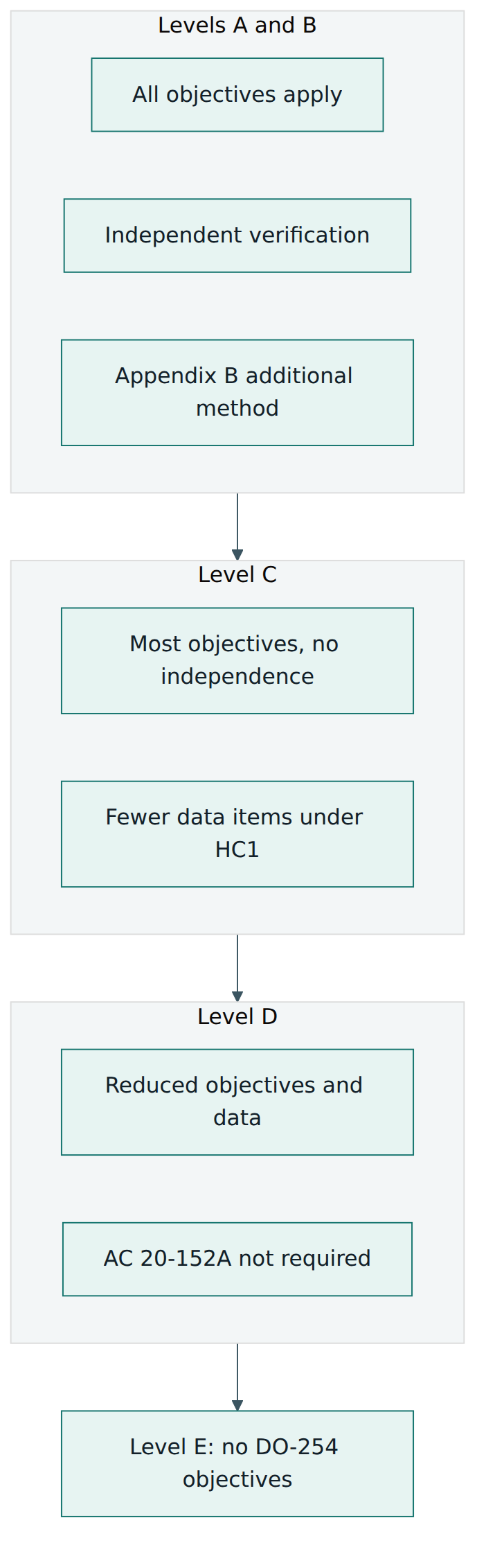
Figure 4 is a simplification: the exact data items and control categories per level are set in Appendix A and refined by AC 20-152A, and authorities can add project-specific expectations through issue papers (FAA) or certification review items (EASA). The general shape, however, holds: most of the cost difference between levels comes from independence, Appendix B methods and the depth of verification and traceability.
Lesson 6 – Worked example
This example is fictional but realistic. It shows how the concepts fit together on one project.
The situation
Northfield Avionics designs a remote electronics unit that sits next to a hydraulic actuator in the wing of a regional aircraft. The unit receives position commands from the flight control computers over a digital data bus, drives the actuator's servo valve and reports the measured position back. At the heart of the unit is an FPGA that decodes commands, runs a monitoring function that detects disagreement between command and position, and controls the valve driver. The unit's own processor software is developed under DO-178C by another team.
Step 1 – Inherit the level
The aircraft safety assessment identifies an uncommanded movement of this control surface as catastrophic. The system architecture uses the FPGA's monitor to detect and stop such a movement, and the system safety analysis does not credit any other mitigation for this failure mode. The FPGA is therefore assigned DAL A. The team does not argue for a lower level on its own; any change would have to come from a revised system architecture and safety assessment.
Step 2 – Classify and plan
The FPGA has several clock domains, multiple state machines and a data bus interface, so it is clearly complex. The project lead writes the PHAC, stating DAL A, the complex classification with a brief rationale, a V-shaped life cycle with defined transition criteria, the tool list, the use of one soft COTS IP block (a bus receiver core), and the choice of elemental analysis by HDL code coverage plus safety-specific analysis for the IP as the Appendix B methods. The team also writes the design, validation, verification, configuration management and process assurance plans, and an HDL coding standard with rules such as synchronous design, safe state machine encoding and handling of clock domain crossings. The PHAC and plans are sent to the authority before detailed design starts, and a planning review closes with two findings: clarify how post-layout simulation will be used, and add the errata review of the FPGA device itself.
Step 3 – Capture and validate requirements
The system team allocates 40 system requirements to the FPGA. The hardware team refines them into 260 hardware requirements, about 60 of which are derived, such as the behaviour on loss of the data bus, the reset sequence, and the response to a corrupted command word. Because the item is level A, requirements for abnormal and boundary conditions are written explicitly. Each derived requirement is sent to the safety team; one of them, a short delay before the monitor trips, is found to matter for the actuator's response time and is changed after discussion.
Step 4 – Design, implement and review
A conceptual design review confirms the block architecture and the separation of the command path from the monitor, which reduces the chance that a single design error affects both. The engineers write the VHDL, trace each block to the requirements and hold detailed design reviews against the coding standard. After synthesis and place and route, a reviewer checks the tool reports, confirming that no logic was unexpectedly optimised away and that every timing constraint was applied. Static timing analysis is run at the corners of temperature, voltage and process specified by the device manufacturer.
Step 5 – Verify with independence
Verification engineers who did not write the VHDL develop the test cases and procedures from the requirements. Simulation covers the full set of requirements, including abnormal inputs. The programmed FPGA is then tested on a representative board with a data bus generator and an actuator simulator. Some internal requirements cannot be observed at the device pins, so the team uses post-layout simulation for them and justifies this in the verification results. Each test case and procedure is reviewed against the requirement it traces to.
For Appendix B, HDL code coverage is collected during requirements-based simulation. Coverage reaches most statements and branches; the remaining gaps are analysed. One is an unreachable default branch required by the coding standard and is justified; another reveals a missing requirement for a rarely used command, which is added and tested. For the soft IP block, the team performs a safety-specific analysis of the parts of the core that could cause an uncommanded movement, and adds two requirements and tests to cover them.
Step 6 – Assess the tools
The synthesis and place-and-route tools are design tools at level A, but their output is independently assessed by hardware testing and post-layout simulation against all requirements, so no qualification is needed. The simulator's results are cross-checked by the hardware tests for the requirements that are tested on the board; for the few requirements verified only in simulation, the team claims relevant tool history for the simulator and backs it with data on previous use and known problems, as AC 20-152A expects for any history claim. The code coverage tool is used only for elemental analysis, which the tool assessment logic allows without further qualification. All of this is recorded in a tool assessment report referenced from the PHAC.
Step 7 – Control, audit and close
All data is held in a configuration management system. Requirements, VHDL, constraints and the programming file are HC1 items; problem reports track 37 issues found during the project. Process assurance audits each transition, witnesses a sample of hardware tests and performs the conformity review, confirming that the delivered programming file matches the verified build. The hardware configuration index lists every data item and version, and a hardware environment configuration index records the tool versions needed to regenerate the design. The HAS states that all objectives were met, lists one deviation from the verification plan (agreed with the authority) and two open problem reports about documentation typos with no functional effect. After the final review, the authority accepts the FPGA's compliance as part of the unit's approval.
What the example shows
Notice how each concept appeared: the DAL came from the safety assessment; complexity drove the amount of data; derived requirements went back to safety and changed the design; independence, Appendix B and timing analysis reflected level A; tool assessment avoided qualification through independent checks; and the HAS closed the loop with the authority. The project did not succeed because the final tests passed. It succeeded because the evidence showed a disciplined process from the first plan to the last baseline.
Lesson 7 – Relationship to other standards and frameworks
DO-254 is one piece of a larger set of aviation guidance, and it has close relatives in other industries. Understanding the boundaries avoids gaps and duplicated work.
The aviation family
At the top, SAE ARP4754B (EUROCAE ED-79B, published December 2023) describes how aircraft and systems are developed, how requirements are allocated, and how development assurance levels are assigned to functions and items. SAE ARP4761A (EUROCAE ED-135) describes the safety assessment methods that identify and classify failure conditions. These two produce the inputs DO-254 relies on: allocated requirements and a DAL. In the middle, DO-254 covers hardware and DO-178C covers software; they share the same philosophy of planning, objectives, traceability and evidence, and they meet at the hardware-software interface. For an FPGA that runs embedded software on a soft processor core, both apply. DO-160 covers environmental testing of equipment, and DO-330 gives tool qualification guidance that AC 20-152A says may also be used for hardware tools.
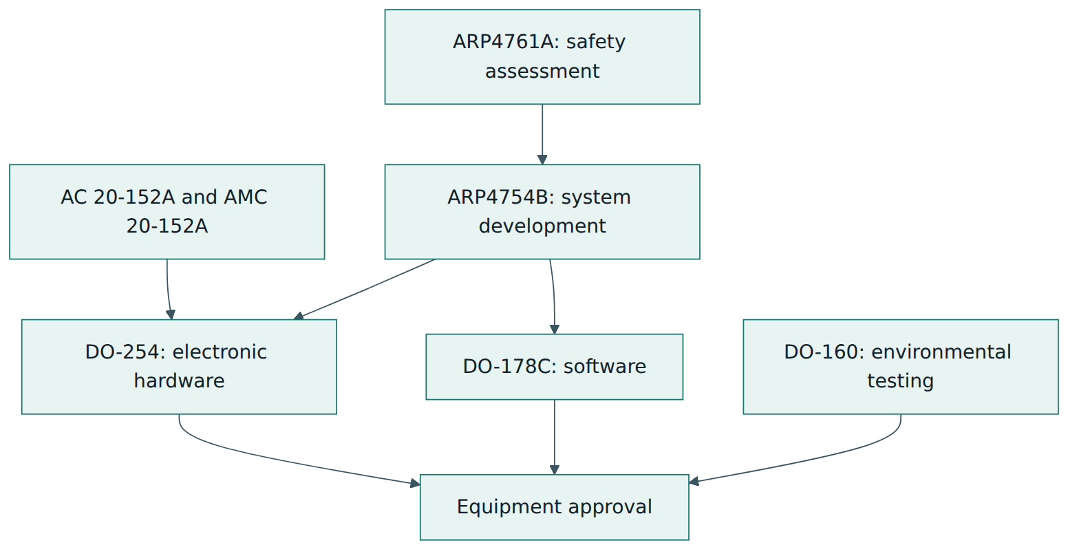
Comparison table
| Standard | What it covers | Relationship to DO-254 |
|---|---|---|
| SAE ARP4754B / EUROCAE ED-79B | Development of civil aircraft and systems, requirement allocation and assignment of development assurance levels | Provides the allocated requirements and the DAL; receives derived requirements back |
| SAE ARP4761A / EUROCAE ED-135 | Safety assessment methods such as functional hazard assessment and fault tree analysis | Classifies the failure conditions that set the hardware level |
| RTCA DO-178C / EUROCAE ED-12C | Software considerations in airborne systems and equipment certification | The software counterpart, with similar objectives and data; the two meet at the hardware-software interface |
| FAA AC 20-152A / EASA AMC 20-152A | Regulator recognition of DO-254 plus 28 additional objectives for custom devices, COTS IP, COTS devices and circuit boards | Defines when and how DO-254 is applied today; read the two together |
| RTCA DO-160 / EUROCAE ED-14 | Environmental conditions and test procedures for airborne equipment | Covers physical robustness, which DO-254 deliberately leaves out |
| ISO 26262 | Functional safety of road vehicle electrical and electronic systems, including hardware | Similar aims in automotive, but adds quantitative hardware metrics for random failures and uses ASILs instead of DALs |
| IEC 61508 | Generic functional safety of electrical, electronic and programmable electronic systems | The cross-industry parent of many safety standards; uses safety integrity levels and covers random as well as systematic failures |
What to take from the comparison
DO-254 is narrower than the automotive and industrial functional safety standards: it focuses on design errors and leaves random hardware failure rates to the safety assessment. Teams moving between industries often find the processes familiar (requirements, traceability, independence, configuration management) but need to adjust to aviation's emphasis on authority involvement, planning documents agreed in advance and objective-by-objective evidence. Within aviation, the most common mistake is treating DO-254 as standalone: without the system and safety inputs, and without AC 20-152A, a hardware team cannot know its level, its full set of objectives or the authority's expectations.
Common pitfalls and best practices
Common pitfalls:
- Starting design before the plans are agreed. Teams that write the PHAC at the end discover that the authority wants a different Appendix B method or tool approach, and must redo verification.
- Weak or untestable requirements. Requirements that restate the design ("signal X is registered") or that omit abnormal conditions make requirements-based verification meaningless and coverage gaps hard to explain.
- Not feeding derived requirements back. Design decisions that change behaviour under failure stay invisible to the safety team until an authority review or, worse, an in-service event.
- Treating code coverage as proof of complete testing. HDL coverage shows which code was exercised by requirements-based simulation; it does not show that the requirements themselves are complete or that the tests checked the right results.
- Relying on simulation only. Without testing the programmed device in a representative environment, the physical implementation and timing behaviour remain unverified.
- Assuming a "DO-254 compliant" IP block or device needs no work. The applicant still owns integration, requirements, verification and, at levels A and B, the Appendix B analysis.
- Uncontrolled tool and environment versions. If the exact synthesis tool version and settings are not recorded, the design cannot be regenerated or modified with confidence years later.
Best practices:
- Engage the authority early. Share the PHAC as soon as the approach is clear and agree the level of involvement, review points and any novel methods.
- Write a strong HDL coding standard and enforce it with linting tools. Rules on synchronous design, reset, state machine safety and clock domain crossings prevent whole classes of errors.
- Plan verification from the requirements, not from the code. Keep verification engineers independent and involve them in requirement reviews so each requirement is verifiable.
- Combine simulation, hardware test and timing analysis deliberately. Decide which requirements each method covers and justify any requirement not tested on hardware.
- Automate traceability and configuration management. A requirements tool linked to test results and a version control system make reviews, audits and changes far cheaper.
- Review the device errata and tool reports routinely. Known device defects and tool warnings are cheap to handle when found early.
- Keep the hardware environment configuration index current. Record tool versions, licences and settings so the design can be rebuilt for future changes or obsolescence work.
Summary and key takeaways
- DO-254 (RTCA, 2000; identical to EUROCAE ED-80) is objective-based guidance for preventing and detecting design errors in airborne electronic hardware; it has one edition, and a revision is being scoped by RTCA SC-243 with EUROCAE WG-128.
- Regulators apply it through FAA AC 20-152A and EASA AMC 20-152A, which add 28 objectives for custom devices, COTS IP, COTS devices and circuit board assemblies at levels A to C.
- The design assurance level (A to E) comes from the safety assessment of failure conditions and scales the objectives, independence and data required.
- The life cycle is planning, five design processes (requirements capture to production transition) and four supporting processes that run throughout.
- Verification is requirements-based; levels A and B add independence and an Appendix B method such as elemental analysis, safety-specific analysis, formal methods or architectural mitigation.
- Tools, COTS IP and COTS devices need explicit assessment; independent checking of tool output usually avoids tool qualification.
- There is no stand-alone DO-254 certificate: compliance is accepted by the authority as part of a TC, STC or TSO approval, through reviews and the PHAC and HAS.
- DO-254 depends on ARP4754B and ARP4761A for inputs and works alongside DO-178C and DO-160.
Reflection questions
- Pick an electronic function in an aircraft you know, such as a landing gear indicator or an engine controller. What would be the worst effect of a design error, and which design assurance level would you expect?
- Think of an FPGA or circuit design you have worked on. Which of its behaviours would become derived requirements under DO-254, and which of those might matter to a safety engineer?
- Your project uses a purchased IP block with limited documentation at level B. What information would you ask the vendor for, and how would you plan its verification?
- Your team wants to avoid qualifying its synthesis tool. How would you argue that the tool output is independently assessed, and what evidence would you keep?
- Compare DO-254 with a safety or quality standard you already use. Which practices would carry over directly, and which would be new for your team?
Further reading and official sources
- AC 20-152A, Development Assurance for Airborne Electronic Hardware – Federal Aviation Administration
- AC 00-72, Best Practices for Airborne Electronic Hardware Design Assurance Using EUROCAE ED-80( ) and RTCA DO-254( ) – Federal Aviation Administration
- Order 8110.105B, Airborne Electronic Hardware Approval Guidelines – Federal Aviation Administration
- EASA publishes new AMCs on development assurance for airborne electronic hardware – European Union Aviation Safety Agency
- SC-243, Airborne Electronic Hardware Development Assurance – RTCA
- ARP4754B, Guidelines for Development of Civil Aircraft and Systems – SAE International
Original tutorial by xOps School (DevOpsSchool Private Limited), written from public sources about DO-254. Not affiliated with or endorsed by the standard's owner; standard names are trademarks of their owners. Buy the official standard from its publisher for the authoritative text.