
IEC 61511 – Tutorial (about 60 minutes)
- View
IEC 61511 is the international standard for safety instrumented systems in the process industries: the trip and shutdown systems that act automatically when a chemical plant, refinery, gas terminal or pharmaceutical site drifts towards a dangerous state. It is used by plant owners and operators, engineering contractors, system integrators, process safety engineers and the people who test and maintain these systems for decades. After this tutorial you will be able to explain what a safety instrumented system is, follow the safety lifecycle from hazard analysis to decommissioning, understand how a safety integrity level is set and verified, and recognise what credible evidence of compliance looks like.
Course overview
Edition and status: the current edition is IEC 61511 Edition 2.0 (2016), Functional safety – Safety instrumented systems for the process industry sector, published by the International Electrotechnical Commission (IEC) and maintained by technical committee TC 65, subcommittee SC 65A (system aspects). The normative core, Part 1, was published in February 2016 and amended in 2017; IEC sells it as the consolidated version IEC 61511-1:2016+AMD1:2017. Part 2 (guidelines for applying Part 1) and Part 3 (guidance on determining the required safety integrity levels) were published in July 2016. Two informative technical reports complete the family: IEC TR 61511-0:2018 and IEC TR 61511-4:2020. IEC lists a stability date of 2029 for Parts 1 to 3, and in July 2026 it issued a bundle of all parts (IEC 61511:2026 SER) that repackages these same documents; it is not a new edition. No third edition has been published. Edition 2.0 is the edition to apply and the one this course teaches. Verified 2026-10-29 against the IEC webstore entries for IEC 61511-1, -2, -3 and the IEC 61511 series.
Who it is for: process, control, instrumentation and electrical engineers; process safety and HSE specialists; operations and maintenance supervisors; project managers and buyers of safety systems; and auditors who meet IEC 61511 for the first time, for example because a HAZOP study has called for a "SIL 2 trip", because a regulator has asked how a plant manages its shutdown systems, or because a supplier claims its equipment is "SIL capable".
Prerequisites: none. A rough idea of how a process plant is controlled (instruments measure, a controller decides, valves and pumps act) helps. Simple arithmetic with powers of ten is used in Lessons 2, 4 and 6, and every term is explained when it first appears.
By the end of this tutorial:
- You will be able to explain what functional safety means in a process plant and why IEC 61511 exists.
- You will be able to define the core vocabulary: safety instrumented system and function, protection layer, safety integrity level, demand mode, proof test, process safety time and prior use.
- You will be able to describe the parts of the IEC 61511 family and the main clauses of Part 1.
- You will be able to walk through the safety lifecycle and name the key documents, roles and checkpoints.
- You will be able to explain how the required safety integrity level is determined and how a design is shown to meet it.
- You will be able to distinguish verification, validation, functional safety assessment and audit, and judge a compliance claim.
- You will be able to place IEC 61511 next to IEC 61508, ANSI/ISA-61511, IEC 62443 and other related standards.
Lesson 1 – Origins, purpose and scope
Why process plants need instrumented protection
A process plant handles large quantities of energy and hazardous material: flammable hydrocarbons, toxic gases, reactive chemicals, steam at high pressure. Most of the time the plant is kept in a safe operating window by its normal control system. Level controllers open and close valves, temperature controllers adjust heating, compressors are kept away from surge. But control systems fail. A transmitter freezes at an old reading, a valve sticks, an operator selects the wrong tank, a software change has an unexpected side effect. When that happens, the process can move quickly towards an overflow, an overpressure, a runaway reaction or a toxic release.
Plants therefore add independent layers of protection. Some are passive, such as a bund (a containment wall) around a tank. Some are mechanical, such as a pressure relief valve. A growing share are instrumented: a dedicated sensor detects the abnormal condition, a dedicated logic solver decides, and a dedicated valve closes or a motor stops. These systems protect only if they work at the rare moment they are needed, after perhaps years of sitting quietly. That reliance on equipment working correctly on demand is what "functional safety" refers to: the part of overall safety that depends on a system or equipment operating correctly in response to its inputs.
Major accidents have shown what happens when this goes wrong. In the 2005 Texas City refinery explosion, a distillation tower was overfilled during start-up while level indication misled the operators. In the same year at the Buncefield fuel depot in England, a storage tank overflowed because its level gauge stuck and the independent high-level switch meant to stop filling did not work, leading to a vapour cloud explosion. In both cases, instruments that should have revealed or stopped the hazard were not managed as safety-critical equipment over their whole life. IEC 61511 exists to make that lifecycle management systematic.
From IEC 61508 to a process-sector standard
The parent standard, IEC 61508, sets out a generic approach to functional safety for electrical, electronic and programmable electronic (E/E/PE) safety-related systems in any industry. It is written mainly for people who design and build such systems and the devices inside them. A process plant owner, however, rarely designs a logic solver or a transmitter from scratch. Instead the owner selects existing devices, configures them, writes an application program in a restricted programming environment, and then operates and maintains the system for twenty or thirty years. The process industry needed a version of the IEC 61508 principles expressed in its own terms and focused on these activities. That is IEC 61511, a sector implementation of IEC 61508.
The first edition appeared in 2003 and was quickly adopted around the world. In the United States it was adopted as ANSI/ISA-84.00.01-2004, building on the earlier ISA 84 standard from 1996. The second edition of 2016 clarified many requirements and added important new ones: a mandatory security risk assessment for the safety instrumented system, stronger competence requirements, simplified rules for hardware fault tolerance, clearer requirements for application programming, and a stronger focus on the operation and maintenance phase, where most of the life of a system is spent.
Scope
IEC 61511 applies to safety instrumented systems in the process industry sector: oil and gas production, refining, petrochemicals, chemicals, pharmaceuticals, pulp and paper, non-nuclear power generation and similar industries that convert materials by chemical or physical processes. It covers systems whose logic solver uses electrical, electronic or programmable electronic technology. The sensors and final elements may use any technology; a pneumatically actuated valve is common. Purely pneumatic or hydraulic logic is outside the scope. Nuclear facilities are covered by their own sector standards.
The standard addresses the end user, integrator and designer of the system, not the manufacturer developing a new device. A manufacturer who develops a new safety controller or a new smart transmitter for safety use follows IEC 61508. The plant team then selects that device, either because it has been shown to comply with IEC 61508 or because there is enough documented evidence of good performance from prior use in similar service. This split of responsibilities is one of the most important ideas in the standard and is shown in Figure 1.
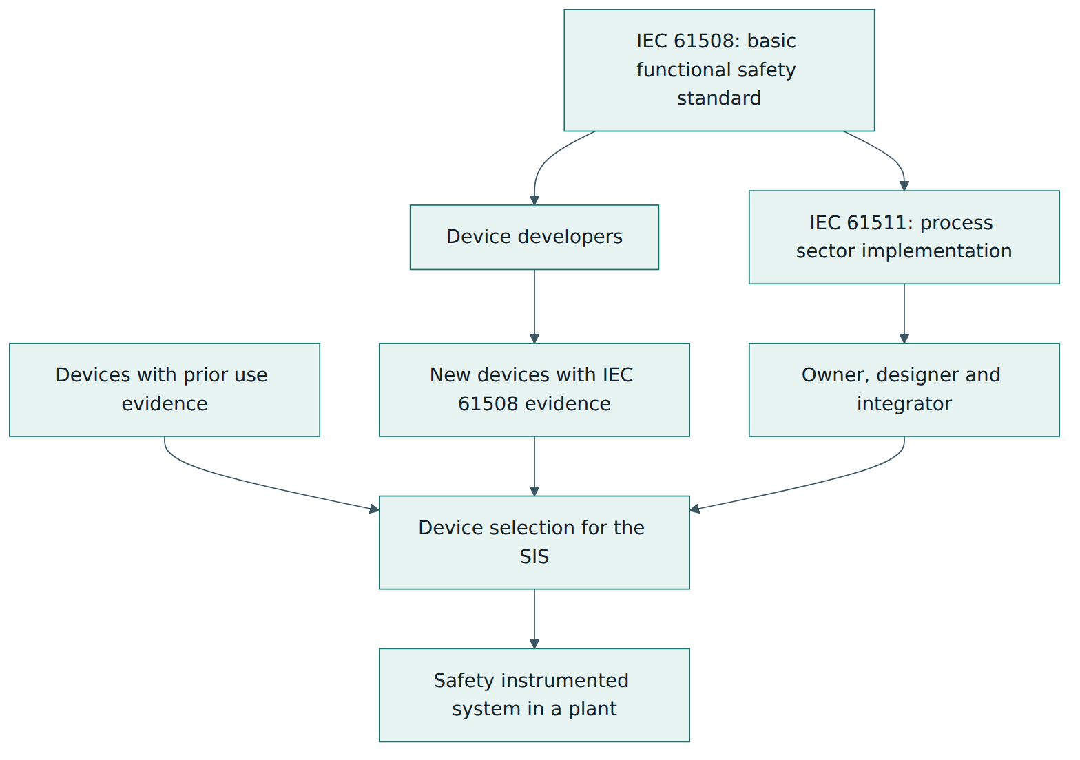
IEC 61511 is performance-based rather than prescriptive. It does not say "use two transmitters" or "test every six months". It says: analyse your hazards, decide how much risk reduction each safety function must provide, design to meet that target, prove that you have met it, and keep it that way throughout the life of the plant. The engineering choices remain yours, but each one must be justified and documented.
Lesson 2 – Key concepts and vocabulary
IEC 61511 has a large and precise vocabulary. The terms below are explained in our own words; the standard's Part 1 contains the formal definitions.
- Hazard – a potential source of harm, such as a large inventory of a flammable liquid or a reaction that can run away.
- Risk – the combination of how often harm is expected to occur and how severe it would be. Risk can be reduced by making the event less likely, less severe, or both.
- Tolerable risk – the level of risk the organisation, guided by law and societal expectations, accepts for a given type of harm. Setting it is the owner's responsibility; IEC 61511 does not set numerical values.
- Basic process control system (BPCS) – the normal control system that runs the plant. It keeps the process within its operating window but is not, by default, designed to the rigour of a safety system.
- Protection layer – any independent measure that reduces risk, such as an alarm with operator response, a safety instrumented function, a relief valve or a dike. A layer counts as independent only if its failure is not caused by the same fault that starts the scenario or disables another layer.
- Safety instrumented system (SIS) – the instrumented system that implements one or more safety functions: sensors, logic solver and final elements, plus supporting items such as power, wiring and the human-machine interface.
- Safety instrumented function (SIF) – one specific protective function with a defined trigger and action, for example "on high-high reactor temperature, close the feed valve and open the cooling water valve within 10 seconds". One SIS usually carries many SIFs.
- Safe state – the process condition that has to be reached and held to prevent the hazardous event, such as "feed stopped and vessel isolated".
- Safety integrity level (SIL) – one of four discrete bands (SIL 1 to SIL 4) that express how much risk reduction a SIF must achieve. Each step up demands roughly ten times more reliability. In the process sector SIL 1 and SIL 2 are most common, SIL 3 is used for severe scenarios, and SIL 4 is so exceptional that the standard asks you to look hard for other ways of reducing the risk.
- Demand mode – how often the SIF is called on. In low demand mode it acts no more than once per year; in high demand mode more often; in continuous mode it acts all the time as part of normal operation. Most process SIFs are low demand.
- Average probability of failure on demand (PFDavg) – for a low demand SIF, the average probability that it will fail to work when called on. Its inverse is the risk reduction factor (RRF): a PFDavg of 0.01 means an RRF of 100.
- Average frequency of dangerous failure per hour (PFH) – the measure used for SIFs in high demand or continuous mode.
- Process safety time – the time between a failure that starts a hazardous scenario and the moment the hazardous event would occur if nothing intervened. The SIF must detect, decide and bring the process to the safe state well within it.
- Proof test – a periodic test that reveals dangerous failures not found by automatic diagnostics, so that they can be repaired. Proof test coverage is the share of those hidden failures a given test procedure can actually reveal.
- Hardware fault tolerance (HFT) – the number of dangerous faults a subsystem can tolerate and still perform its function. A single transmitter has HFT 0; two transmitters where either can trip (one-out-of-two, written 1oo2) have HFT 1.
- Prior use – documented evidence, from operating experience in a similar environment and application, that a device is suitable for a safety duty. It is the process-sector alternative to IEC 61508 compliance evidence for a device.
- Safety requirements specification (SRS) – the document that states what each SIF must do and how well: trip points, actions, response times, SIL, proof test intervals, bypass rules, reset behaviour and more.
- Spurious trip – a shutdown caused by a SIS fault rather than a real hazard. It costs production, can create hazards during restart, and tempts people to bypass the SIS.
Two kinds of failure
IEC 61511, like IEC 61508, distinguishes two kinds of failure. Random hardware failures occur at unpredictable times because of physical wear, stress or ageing; across a population of devices they follow statistical patterns and can be estimated with failure rates. Systematic failures are built in by errors in specification, design, application programming, installation, operation or maintenance; they will occur every time the same conditions arise. A trip setpoint entered in the wrong units or a transmitter left isolated after maintenance are systematic failures. Probability calculations deal with random failures. Systematic failures are prevented by the lifecycle, competence, procedures, independent checks and management of change. This is why most of IEC 61511 is about how work is done, not about arithmetic.
SIL bands for low demand mode
For a low demand SIF, the bands are defined by PFDavg. SIL 1 covers a PFDavg from 0.1 down to 0.01 (risk reduction of 10 to 100). SIL 2 covers 0.01 down to 0.001 (100 to 1,000). SIL 3 covers 0.001 down to 0.0001 (1,000 to 10,000). SIL 4 covers the next decade. For high demand or continuous SIFs, equivalent bands are defined in terms of dangerous failures per hour. A SIL is not a property of a single device; it belongs to a whole function, from the sensor through the logic to the final element.
Lesson 3 – Structure of the standard
The IEC 61511 family
IEC 61511 Edition 2 consists of three numbered parts plus two technical reports:
- Part 1 – framework, definitions, system, hardware and application programming requirements. This is the normative part: it contains the requirements ("shall" statements) that a claim of conformance is judged against.
- Part 2 – guidelines for the application of Part 1. Informative: it explains the intent of Part 1 requirements and gives examples across the lifecycle.
- Part 3 – guidance for determining the required safety integrity levels. Informative: it illustrates hazard and risk assessment approaches such as semi-quantitative methods, layer of protection analysis, risk graphs and a safety layer matrix. It provides a framework but does not set the SIL for any particular application.
- IEC TR 61511-0 (2018) – an informative technical report that introduces functional safety in the process sector and how the series fits together.
- IEC TR 61511-4 (2020) – an informative technical report explaining the rationale for the clauses of Part 1 and for the changes from the first to the second edition.
National bodies republish the standard: in Europe it is EN 61511 (for example BS EN 61511 in the UK), and in the United States it is ANSI/ISA-61511, which adopts the IEC text with a US modification for existing systems. The technical content of these adoptions follows the IEC text.
The main clauses of Part 1
Part 1 is organised largely in lifecycle order. After the usual opening clauses (scope, normative references, terms and abbreviations), the main requirements are grouped as follows (titles paraphrased):
- Clause 4 – Conformance: what it means to conform to the standard.
- Clause 5 – Management of functional safety: policy, organisation and responsibilities, competence, planning, implementation and monitoring, functional safety assessment and audit, configuration management.
- Clause 6 – Safety lifecycle requirements: the need to define a lifecycle with inputs, outputs and verification for each phase.
- Clause 7 – Verification: planning and performing checks that each phase delivered what it should.
- Clause 8 – Process hazard and risk assessment: identifying hazards, hazardous events and the need for risk reduction, including the SIS security risk assessment.
- Clause 9 – Allocation of safety functions to protection layers: deciding which layer does what, setting SIL targets and the rules for claiming risk reduction from the BPCS.
- Clause 10 – SIS safety requirements specification: what the SRS must contain.
- Clause 11 – SIS design and engineering: independence, hardware fault tolerance, device selection, field devices, interfaces, maintenance and testing provisions, and SIL verification calculations.
- Clause 12 – Application program development: requirements, design, coding, testing and verification of the application logic.
- Clause 13 – Factory acceptance testing: testing the logic solver and its program before shipping to site.
- Clause 14 – Installation and commissioning.
- Clause 15 – Safety validation: proving the installed SIS meets the SRS.
- Clause 16 – Operation and maintenance: training, procedures, proof testing, bypass control, recording demands and failures.
- Clause 17 – Modification: management of change for the SIS.
- Clause 18 – Decommissioning.
- Clause 19 – Information and documentation requirements.
Three types of programming language
Part 1 recognises that SIS programming in the process sector usually happens in restricted environments. It distinguishes fixed program languages, where the user only sets parameters (for example the range of a transmitter); limited variability languages, such as function block diagrams or ladder logic in a safety PLC, which use a library of pre-certified blocks; and full variability languages, such as general-purpose programming languages. Part 1 covers application programming with the first two. If full variability languages are used to build the system, the software requirements of IEC 61508-3 apply instead.
Lesson 4 – How it works in practice
The safety lifecycle
The heart of IEC 61511 is the SIS safety lifecycle. It is a set of phases, each with defined inputs, outputs and verification, that runs from the first hazard study to the day the system is removed. Figure 2 shows the main phases. Running alongside all of them are management of functional safety, safety planning, verification, and functional safety assessment.
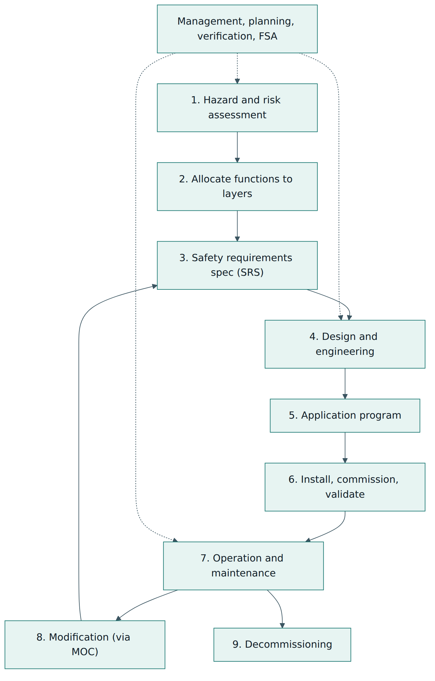
Step 1: hazard and risk assessment
Everything starts with understanding what can go wrong. Teams typically use a hazard and operability study (HAZOP), in which a multidisciplinary group works through the process design and asks how deviations such as "more flow", "no flow" or "high temperature" could arise and what the consequences would be. For each hazardous event, the team records the causes (initiating events), consequences and the safeguards that already exist. The 2016 edition also requires a security risk assessment for the SIS: how could someone, deliberately or accidentally, compromise the SIS through its networks, engineering workstations or remote access, and what countermeasures are needed?
Step 2: allocation to protection layers and SIL determination
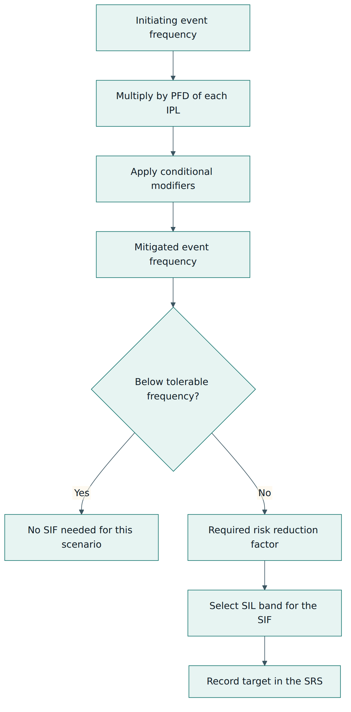
Next, the team decides how much additional risk reduction each scenario needs and which protection layers will provide it. The most common method in the process industry is layer of protection analysis (LOPA), a semi-quantitative technique developed by the US Center for Chemical Process Safety and illustrated in Part 3. LOPA works with orders of magnitude:
- Estimate the frequency of the initiating event, for example a control loop failure once in ten years (0.1 per year).
- Credit each existing independent protection layer (IPL) with its probability of failure on demand: an alarm with operator response might be credited with 0.1, a properly sized relief valve with 0.01.
- Optionally apply conditional modifiers, such as the probability that a release ignites or that someone is present.
- Multiply to obtain the mitigated event frequency and compare it with the tolerable frequency the company has set for that consequence.
- If the gap is too large, the ratio between them is the risk reduction a new SIF must provide, which sets its SIL.
An important rule in this phase limits how much risk reduction you can claim from the BPCS. Because the normal control system is not designed to safety standards, IEC 61511 caps the credit for a BPCS protection layer at a risk reduction factor of 10, unless that layer is itself designed and managed according to the standard. And if a BPCS failure is the initiating cause, any BPCS protection layer claimed against it must be independent of that failure: equipment that has just failed cannot also be counted as protecting against it. These rules stop a team from "designing away" the need for a SIS on paper.
Step 3: the safety requirements specification
The SRS is the contract between the hazard study and the engineering team. For every SIF it states, among other things: the hazardous event it prevents; the process measurements and trip points; the actions and the safe state; the required SIL and demand mode; the response time compared with the process safety time; the proof test interval; how bypasses, resets and manual shutdowns work; what happens on loss of power, air or diagnostics; the acceptable spurious trip rate; and the environmental conditions. A vague SRS is one of the most common root causes of SIS problems, because everything downstream is designed and tested against it.
Step 4: design and engineering
The designer turns the SRS into hardware and software. Key decisions include:
- Independence from the BPCS. A SIS should normally use its own sensors, logic solver and final elements. Sharing is possible only with careful analysis showing that a single failure cannot both start the scenario and defeat the protection.
- Device selection. Each device needs either IEC 61508 compliance evidence (often a certificate and a safety manual from the manufacturer) or documented prior use evidence. The device's safety manual must be followed.
- Architecture and hardware fault tolerance. Part 1 sets minimum HFT by SIL: zero for SIL 1, zero for SIL 2 in low demand mode, one for SIL 2 in high demand or continuous mode, one for SIL 3 and two for SIL 4. Designers may alternatively meet the architectural requirements of IEC 61508-2. Redundancy is also often added to meet the PFDavg target or to reduce spurious trips, for instance two-out-of-three (2oo3) voting on transmitters.
- SIL verification. A calculation, using failure rates, diagnostic coverage, proof test interval and coverage, repair time and common cause factors, shows that the PFDavg of each SIF is low enough to meet its required risk reduction, not just to land somewhere in the SIL band.
- Systematic capability. Each device must be suitable for the SIL of the function it serves, either through IEC 61508 systematic capability or prior use.
- Testing and maintenance provisions: test connections, bypass facilities with alarms, and access for maintenance.
Step 5: application program development
The logic is specified, designed, coded, reviewed and tested following a planned approach. Good practice includes using standard function blocks, keeping the logic simple and traceable to the SRS, and testing every SIF's trip path, reset and bypass behaviour. Clause 13's factory acceptance test (FAT) checks the logic solver and program together before they leave the integrator's workshop.
Step 6: installation, commissioning and validation
On site, the team confirms that everything has been installed as designed, that wiring and tubing are correct, and that instruments are calibrated. Safety validation then demonstrates, through tests on the installed system, that every SIF performs exactly as the SRS requires, end to end, from a real or simulated process signal to the final element reaching the safe state within the required time.
Step 7: operation and maintenance
This is where the system spends most of its life and where its integrity can quietly erode. Operators must be trained to understand the SIFs, their alarms and what to do after a trip. Maintenance must perform proof tests at the intervals assumed in the SIL verification, with procedures that reveal the failures the calculation expects to find. Bypasses must be authorised, time-limited, logged and compensated by other measures. Demands on the SIS, failures found in tests and spurious trips must be recorded and analysed, and the real performance compared with the design assumptions.
Steps 8 and 9: modification and decommissioning
Any change to the SIS or to the process it protects (a new trip point, a larger pump, a software change, a replacement device of a different type) goes through management of change. The impact is analysed and the lifecycle is re-entered at the appropriate phase. Decommissioning also needs care, because removing a SIF or a whole SIS changes the risk picture for the remaining plant.
Management of functional safety
Clause 5 wraps all of this in a management system. The organisation needs a functional safety policy, named responsibilities, a functional safety management plan for each project and for operations, competent people (competence is defined in terms of knowledge, experience and training relevant to the tasks), configuration management, and procedures for verification, assessment and audit.
Anatomy of a SIF
It helps to picture one SIF as a chain. Figure 4 shows the elements that must all work for the function to succeed: if any link fails dangerously, the whole function fails.
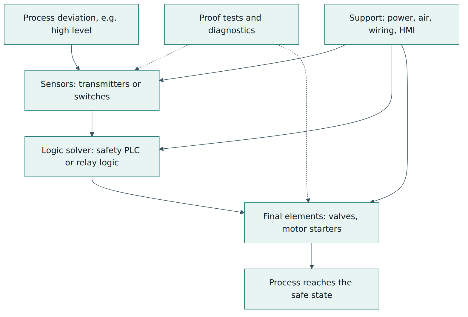
In practice the final elements, especially valves, usually dominate the PFDavg, because they sit still for months, can stick, and are hard to test fully without stopping the process. This is why valve selection, partial stroke testing and realistic proof test coverage receive so much attention.
Lesson 5 – Assessment, certification and compliance
Four kinds of checking
IEC 61511 uses four related but different kinds of check, and confusing them is a classic beginner mistake.
- Verification asks, phase by phase, "did we do this phase correctly, and is its output consistent with its input?" Examples: reviewing the SRS against the LOPA results, checking the SIL verification calculation, reviewing the application program against the SRS.
- Validation asks, once the SIS is installed, "does the system as built do what the SRS requires?" It is demonstrated by end-to-end testing on the real installation.
- Functional safety assessment (FSA) is an independent investigation that judges whether functional safety has actually been achieved at a given stage. It is performed by a team that includes at least one senior, competent person who is not part of the project design team.
- Functional safety audit checks whether the procedures required by the functional safety management system are actually being followed, typically through records and interviews.
The five FSA stages
Part 1 describes five points in the lifecycle where an FSA can take place. Stage 1 follows the hazard and risk assessment, the allocation to protection layers and the SRS. Stage 2 follows the SIS design. Stage 3 follows installation, commissioning and validation, once operating and maintenance procedures exist. Stage 4 takes place after experience has been gained in operation and maintenance. Stage 5 follows a modification and comes before decommissioning. The stage 3 assessment is mandatory and must be completed before the hazards are present, in other words before the plant starts up with process material that the SIS must protect against. The 2016 edition also expects assessment to be repeated periodically during the operation and maintenance phase, recognising that integrity can decline over time. Earlier assessments are wise on larger or novel projects, because errors found at stage 1 are far cheaper to fix.
Is there an "IEC 61511 certificate"?
There is no single certification scheme for a plant equivalent to an ISO 9001 or ISO/IEC 27001 management system certificate. Compliance with IEC 61511 is demonstrated by the owner's own evidence: the hazard studies, LOPA, SRS, SIL verification, verification records, validation records, FSA reports, proof test records and management of change files. What does exist is a set of related schemes:
- Product certification of devices such as safety PLCs, transmitters and valves against IEC 61508, issued by accredited certification bodies, usually with a stated systematic capability and failure data. This supports device selection under IEC 61511 but does not make the SIF compliant by itself.
- Functional safety management certification of companies (often integrators or engineering contractors) by independent bodies, attesting that their processes meet the relevant requirements of IEC 61511 or IEC 61508.
- Personnel certification programmes for functional safety engineers and technicians, run by several independent organisations, which help demonstrate competence but are not required by the standard itself.
Regulators and the law
IEC 61511 is a voluntary standard, but regulators widely treat it as the benchmark of good practice. In Great Britain, the Health and Safety Executive regards BS EN 61511 as relevant good practice for safety instrumented systems at major hazard sites. In the United States, the ANSI/ISA-61511 adoption (developed by the ISA84 committee) is widely treated as recognised and generally accepted good engineering practice under process safety management regulation. In practice, a major hazard operator who cannot show IEC 61511-style lifecycle evidence for its trip systems will struggle to convince an inspector that the risk is properly controlled.
Existing systems
Many plants have safety systems installed before the current edition. The owner is expected to show that such equipment is designed, maintained, tested and operated safely; the US adoption makes this explicit. The usual response is a gap assessment followed by planned upgrades.
What credible evidence looks like
When someone says "our SIS is IEC 61511 compliant", useful follow-up questions are: Which hazard studies set the SIL targets, and are they current? Is there an SRS for each SIF? Where are the SIL verification calculations, and what proof test intervals and coverage did they assume? Are proof tests done on schedule with those procedures? Who performed the stage 3 FSA, and how independent were they? How are bypasses controlled? What do the demand and failure records show? A certificate on a logic solver answers none of these questions.
Lesson 6 – Worked example
Consider a fictional specialty chemicals site, "Rivermouth Solvents", that is adding a new 200 cubic metre day tank for a flammable solvent. The tank is filled by a transfer pump from bulk storage and empties continuously into the plant. The BPCS controls the level using a level transmitter and a control valve on the filling line. The site has a functional safety management plan and a designated functional safety lead. Here is how the project applies IEC 61511.
Hazard and risk assessment
The HAZOP team examines "more level" and identifies a credible scenario: the BPCS level transmitter fails reading low, the control valve stays open, and the tank overflows into its bund. A large spill of flammable solvent forms a vapour cloud that could ignite and seriously injure workers nearby. The team records the existing safeguards: the bund (which contains liquid but does not prevent the vapour cloud), and a high-level alarm generated by the BPCS from the same transmitter. The SIS security risk assessment, performed at the same time, notes that the SIS engineering workstation will sit on the control network and calls for network segregation, controlled remote access and change logging.
LOPA and SIL target
The LOPA team uses the site's calibrated data:
- Initiating event: BPCS level loop failure, 0.1 per year.
- The BPCS high-level alarm uses the failed transmitter, so it is not independent of the initiating event and earns no credit. The team decides to add a separate high-level alarm from an independent instrument, with a documented operator response and enough time to act. It credits this IPL with a PFD of 0.1.
- Conditional modifier: probability of ignition of a large solvent cloud, taken as 0.3 from the site's guidance.
- Mitigated event frequency without a SIF: 0.1 × 0.1 × 0.3 = 0.003 per year.
- The company's tolerable frequency for an event that may cause a fatality: 0.00001 per year (1 in 100,000 years).
The required risk reduction from a new SIF is 0.003 / 0.00001 = 300, so the SIF needs a PFDavg no higher than about 0.0033. That falls in the SIL 2 band (risk reduction 100 to 1,000). The team records "SIL 2, RRF at least 300, low demand mode" as the target. Note that "SIL 2" alone would not be enough: a SIF with a PFDavg of 0.009 would be SIL 2 but would deliver only a risk reduction of about 110.
Safety requirements specification
The SRS entry for the new SIF, tagged SIF-101, specifies: measurement by a dedicated radar level transmitter, independent of the BPCS; trip point at high-high level, chosen so that at the maximum filling rate there are 12 minutes before overflow (the process safety time); action: stop the transfer pump and close a dedicated shut-off valve on the filling line; required response time under 1 minute, including valve stroke; safe state: filling stopped; manual reset only, after the operator confirms the level has fallen; bypass allowed only for proof testing, with permit, alarm and a time limit; proof test interval 12 months; maximum acceptable spurious trip rate once in ten years; behaviour on transmitter fault: alarm and trip if the fault persists.
Design and SIL verification
The design team selects a radar transmitter and a safety PLC, both with IEC 61508 certificates and safety manuals, and a shut-off valve type with a strong prior use record on the site in similar solvent service. For SIL 2 in low demand mode the minimum HFT is zero, so a single transmitter is architecturally acceptable. The first SIL verification calculation, however, shows that a single valve tested once a year leaves the PFDavg too close to the 0.0033 limit, because the valve dominates. The team chooses two independent final elements in a 1oo2 arrangement: tripping the pump motor starter and closing the shut-off valve, either of which stops filling. The recalculated PFDavg, including a common cause factor, realistic proof test coverage and repair times, is 0.0015, which meets the RRF of 300 with margin. The calculation and its assumptions are recorded and verified by a second engineer.
Programming, testing and validation
The integrator writes the logic in the safety PLC's function block language (a limited variability language), using the vendor's certified blocks. The FAT tests every input, trip, reset and bypass against the SRS. On site, after loop checks and calibration, the validation team raises the level signal (simulated at the transmitter and then, for a final check, with a real level rise during commissioning), confirms that the pump stops and the valve closes, and times the full response. An independent FSA stage 3 team, led by a senior engineer from another division, reviews the evidence and confirms that SIF-101 is ready before solvent is introduced into the tank.
Operation, maintenance and change
Operators are trained on the new alarm, the trip and the reset procedure. Each year maintenance performs the proof test: a level test of the transmitter against a reference, a full stroke and leak check of the valve, and a check that the pump starter actually drops out. Results, failures found and any spurious trips go into the SIS performance log. Two years later the site plans a larger transfer pump. The management of change review notes that faster filling shortens the time to overflow from 12 to 8 minutes. The team re-enters the lifecycle at the hazard study and SRS, lowers the trip point, recalculates response time and PFDavg, updates the SRS and test procedures, and carries out a stage 5 FSA before the new pump runs.
Lesson 7 – Relationship to other standards and frameworks
IEC 61511 sits in a family of functional safety and process safety standards. Understanding the neighbours helps you see who does what.
| Standard | Focus | Relationship to IEC 61511 |
|---|---|---|
| IEC 61508 | Basic functional safety standard for E/E/PE safety-related systems in any sector | IEC 61511 is its process sector implementation. Device manufacturers developing new devices follow IEC 61508; full variability software follows IEC 61508-3. |
| ANSI/ISA-61511 (ISA 84) | US adoption of IEC 61511 | Same technical content, with a US modification for existing systems; widely used as good engineering practice in US process safety management. |
| EN 61511 / BS EN 61511 | European and national adoptions | Identical text; referenced by regulators such as the UK HSE as relevant good practice. |
| IEC 62061 and ISO 13849 | Functional safety of machinery control systems | Machinery sector counterparts. Used for packaging lines and machines within process plants rather than for process trips. |
| IEC 61513 | Instrumentation and control for nuclear power plants | Nuclear sector counterpart; nuclear facilities are outside the scope of IEC 61511. |
| IEC 62443 (ISA/IEC 62443) | Cybersecurity of industrial automation and control systems | Provides methods and requirements to carry out and act on the SIS security risk assessment that IEC 61511 requires. |
| IEC 61882 (HAZOP) and LOPA guidance | Hazard identification and risk analysis methods | Feed the hazard and risk assessment and SIL determination phases of the lifecycle. |
| ISA-18.2 / IEC 62682 | Alarm management | Supports credible alarm-and-operator-response protection layers that LOPA may credit. |
IEC 61508 and IEC 61511: a closer look
Beginners often ask which of the two to follow. The answer depends on your role. If you develop a new safety device, IEC 61508 governs your development process and provides the evidence (failure rates, systematic capability, safety manual) that users need. If you design, integrate, install, operate or maintain a SIS in a process plant, IEC 61511 governs your work, and you rely on IEC 61508 only indirectly, through the devices you choose, or directly if you write full variability software.
Functional safety and process safety management
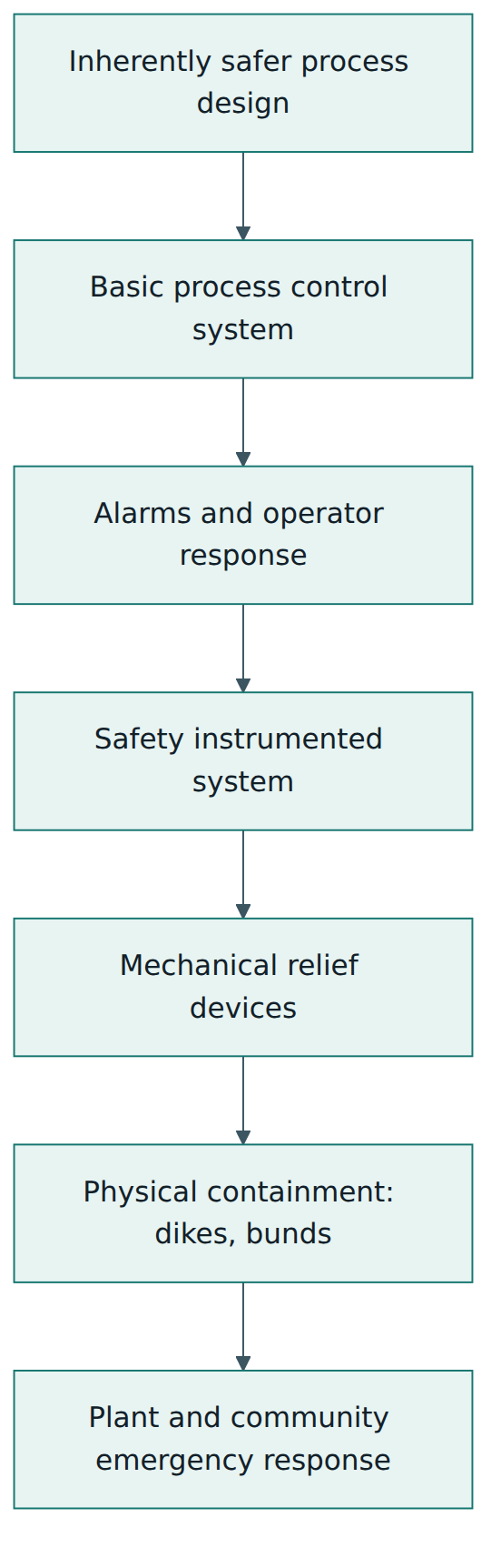
IEC 61511 is one part of a wider process safety management system that also covers process safety information, operating procedures, mechanical integrity, contractor management, incident investigation and emergency response. The SIS is one protection layer among many. Good process safety practice tries to remove hazards by inherently safer design first, then relies on control, alarms, SIS, relief and mitigation in turn, as Figure 5 shows. IEC 61511 asks you to decide what the SIS must achieve in the context of all the other layers.
Common pitfalls and best practices
Common pitfalls
- Treating SIL as a device label. Buying "SIL 3 certified" components does not create a SIL 3 function. The whole function, its architecture, its proof testing and the way it is operated decide the integrity achieved.
- Over-crediting the control system. Claiming several independent layers that all depend on the same BPCS controller, transmitter or operator inflates the apparent protection and leaves the SIS under-designed.
- Optimistic proof test assumptions. A calculation that assumes perfect proof test coverage, while the actual procedure only checks that a valve moves, overstates integrity. Valves that are never tested against process pressure are a frequent example.
- Vague or missing SRS. Without clear trip points, response times, bypass and reset rules, the design and testing teams fill gaps with assumptions that nobody checks.
- Uncontrolled bypasses. Long-standing or forgotten bypasses, often introduced to stop nuisance trips, quietly remove protection. Several major accidents involved disabled or ineffective trips.
- Ignoring the operation phase. Many projects deliver excellent design documents and then never compare actual demand rates, failures and test results with the design assumptions.
Best practices
- Start with good hazard studies and calibrated LOPA rules (initiating event frequencies, IPL credits, tolerable risk criteria) agreed at company level, so that SIL targets are consistent across projects.
- Keep the SIS simple and independent. Fewer, well-defined SIFs with dedicated devices are easier to verify, test and operate than complex logic shared with the BPCS.
- Design for testing. Plan proof test methods, intervals and coverage during design, add test facilities, and use realistic assumptions in the SIL verification.
- Use independent reviewers early. Stage 1 and stage 2 assessments catch specification and design errors when they are cheap to correct.
- Build and record competence for everyone with a lifecycle role, including operators and maintenance technicians, not only design engineers.
- Collect and use performance data. Track demands, spurious trips, failures found in tests and bypass hours, and feed the findings back into designs and failure rate assumptions.
Summary and key takeaways
- IEC 61511 (Edition 2.0, 2016; Part 1 amended 2017) is the process sector standard for safety instrumented systems, built on the principles of IEC 61508.
- A safety instrumented system carries one or more safety instrumented functions, each a chain of sensor, logic solver and final element that must take the process to a safe state in time.
- The required SIL comes from hazard and risk assessment, typically LOPA, by comparing the mitigated event frequency with a tolerable target; credit for the BPCS is strictly limited.
- Meeting a SIL requires the right architecture (minimum hardware fault tolerance), a low enough PFDavg or PFH from verification calculations, and devices with suitable systematic capability or prior use evidence.
- Most SIS failures are systematic, so the lifecycle, the SRS, competence, verification and management of change matter as much as reliability calculations.
- Verification, validation, functional safety assessment and audit are distinct activities; the stage 3 FSA must be completed before hazards are introduced.
- There is no plant-level IEC 61511 certificate; compliance rests on the owner's lifecycle evidence, supported by device, company and personnel certification schemes.
- Operation and maintenance, especially proof testing and bypass control, is where integrity is kept or lost over decades.
Reflection questions
- Pick one shutdown function on a plant you know (or the tank example in Lesson 6). Which independent protection layers protect against the same scenario, and which of them might share a common cause with the initiating event?
- Your LOPA shows a required risk reduction of 80. A colleague suggests simply adding a second operator alarm instead of a SIF. What would you need to know to decide whether that is credible?
- A SIL verification assumes 95 % proof test coverage for a shut-off valve. What would you look for in the actual proof test procedure and records to judge whether that assumption is realistic?
- How would you organise functional safety assessments for a small modification, such as changing a trip setpoint, compared with a new plant? What determines how independent the assessor must be?
- Your site's SIS engineering workstation is used remotely by the vendor for diagnostics. Using what you learned about the security risk assessment, which questions would you raise and which other standard would you consult?
Further reading and official sources
- IEC 61511-1:2016+AMD1:2017 CSV – Framework, definitions, system, hardware and application programming requirements – International Electrotechnical Commission (IEC webstore)
- IEC 61511-2:2016 – Guidelines for the application of IEC 61511-1 – IEC webstore
- IEC 61511-3:2016 – Guidance for the determination of the required safety integrity levels – IEC webstore
- IEC 61511 series – all parts – IEC webstore
- Functional safety – IEC
- ISA84, Instrumented Systems to Achieve Functional Safety in the Process Industries – International Society of Automation
- IEC 61511 overview – Wikipedia
Original tutorial by xOps School (DevOpsSchool Private Limited), written from public sources about IEC 61511. Not affiliated with or endorsed by the standard's owner; standard names are trademarks of their owners. Buy the official standard from its publisher for the authoritative text.