
IEC 62061 – Tutorial (about 60 minutes)
- View
IEC 62061 is the international standard for the functional safety of machinery control systems: the guards, light curtains, emergency stops, safe drives and safety controllers that must stop or prevent hazardous machine motion when something goes wrong. Machine builders, system integrators, controls engineers, safety engineers and the people who buy and operate industrial machines use it to decide how reliable each safety function must be and to prove that the design achieves it. After this tutorial you will be able to explain what the standard covers, set a safety integrity level (SIL) for a safety function, follow the design process from specification to validation, check a design in terms of subsystems and failure rates, and tell a credible claim of compliance from an empty one.
Course overview
Edition and status: the current edition is IEC 62061:2021, Edition 2.0, Safety of machinery – Functional safety of safety-related control systems, published by the International Electrotechnical Commission (IEC) on 22 March 2021 and maintained by technical committee TC 44 (Safety of machinery – Electrotechnical aspects). It is a single-part standard. It replaced the first edition of 2005 and its two amendments (2012 and 2015) and was a full technical revision. Since then IEC has published Amendment 1 (28 March 2024, sold together with the base text as the consolidated version IEC 62061:2021+AMD1:2024, edition 2.1) and a short Amendment 2 (20 March 2026, a 5-page document, also available as a consolidated version IEC 62061:2021+AMD1:2024+AMD2:2026). The IEC webstore shows a stability date of 2028, meaning the committee does not plan to revise the edition before then. The amendments refine the 2021 text rather than replace it; this course teaches the 2021 framework, and you should work from the latest consolidated text when you apply the standard, because individual requirements and annex details may have been adjusted. In Europe the standard is published as EN IEC 62061. Verified 2026-10-29 against the IEC webstore entries for IEC 62061:2021, the consolidated version with Amendment 1, and Amendment 2:2026, and the 61508 Association's overview page.
Who it is for: controls, electrical and mechanical engineers who design machines or production cells; safety and compliance staff who prepare technical files; project managers and buyers who must specify or accept safety performance; and maintenance engineers who modify existing machines. It is equally useful if you already know ISO 13849-1 and want to understand the other machinery functional safety standard.
Prerequisites: none. It helps to know that a control system reads inputs (switches, sensors), makes decisions (relays, controllers) and drives outputs (contactors, valves, motor drives). A little arithmetic with powers of ten is used; every term is explained when it first appears.
By the end of this tutorial:
- You will be able to explain what functional safety means for machinery and where IEC 62061 sits next to IEC 61508 and ISO 13849-1.
- You will be able to use the core vocabulary: safety function, safety-related control system, subsystem, SIL, PFH, hardware fault tolerance, diagnostic coverage and common cause failure.
- You will be able to describe the structure of the standard and the design process it sets out, from functional safety plan to validation and documentation.
- You will be able to determine a required SIL from a risk estimate and check whether a design of subsystems can meet it.
- You will be able to recognise the software, parametrization, periodic testing and independence requirements that the 2021 edition added or expanded.
- You will be able to judge claims of compliance and know what evidence a reviewer or customer should ask for.
- You will be able to choose sensibly between IEC 62061 and ISO 13849-1 and combine them where that makes sense.
Lesson 1 – Origins, purpose and scope
Why machinery needs functional safety
Machines crush, cut, entangle, burn and strike. For more than a century the main defence has been physical: fixed guards, fences, two-hand controls and careful layout. Physical guards are still the first choice where they are practical, but modern production needs people to load parts, clear jams, teach robots and change tools. Fixed guards cannot do all of that, so machines increasingly rely on control functions to protect people: a door switch that stops a spindle when the guard opens, a light curtain that halts a press when a hand crosses its field, a laser scanner that slows an automated guided vehicle, a drive that limits a robot's speed while a person is nearby.
Each of these protections works only if the control system behaves correctly. If a switch contact welds, a wire breaks, a controller freezes or a parameter is changed by mistake, the protection disappears without any visible sign, and the next person who opens the door is exposed. Functional safety is the part of overall safety that depends on such systems working correctly in response to their inputs. A functional safety standard answers two questions: how reliable does each protective function need to be, and how do you design and prove a control system that reaches that reliability?
From a generic standard to a machinery standard
IEC 61508, first published at the end of the 1990s, is the generic "umbrella" standard for functional safety of electrical, electronic and programmable electronic systems. It is thorough but heavy: it was written to cover everything from chemical plant shutdown systems to the design of safety microprocessors. Machine builders needed something more focused. Most of their safety functions operate frequently (a guard door may open hundreds of times per shift), they are built largely from catalogue components, and the people designing them are integrators rather than chip designers.
IEC 62061 was therefore written as the machinery sector standard within the IEC 61508 framework. The first edition appeared in 2005 and dealt with electrical, electronic and programmable electronic control systems. The second edition of 2021 reorganised the text around the design process of a safety function, aligned definitions with IEC 61508, and extended the scope to non-electrical technologies such as hydraulic, pneumatic and mechanical parts of a safety-related control system. It also introduced a functional safety plan, expanded the requirements on parametrization, and added requirements on periodic testing, software use cases and independence of software verification and of validation.
What is in scope and what is not
The standard applies to safety-related control systems used, alone or in combination, to perform safety functions on machines that are not portable by hand while working, including groups of machines that work together in a coordinated way, such as a production line or a robot cell. Its main body addresses safety functions that are demanded often or act continuously, which is typical for machinery.
Several things are deliberately left out. The standard deals only with risks that come from the hazards of the machine itself, not with electric shock from the control equipment (that belongs to IEC 60204-1, the standard on the electrical equipment of machines). It does not cover safeguarding measures that are not control functions, such as fixed guards. It does not specify cybersecurity measures; for those it points to IEC TR 63074, which deals with security aspects related to functional safety of machinery. Finally, it does not tell you how to design complex programmable electronic devices such as a safety PLC or a safety microcontroller: the manufacturers of such devices follow IEC 61508, and the machine builder uses them as finished, pre-assessed building blocks.
Who uses it
The main user is the organisation that designs the machine's safety-related control system: a machine manufacturer, an integrator that combines several machines into a line, or an end user that modifies its own equipment. Component manufacturers use it to describe what their products can contribute (for example "suitable for use up to SIL 3"). Assessors, notified bodies and insurers use it as a yardstick, and buyers use it to write clear requirements into purchase specifications.
Lesson 2 – Key concepts and vocabulary
IEC 62061 uses terms aligned with IEC 61508-4, the vocabulary part of the generic standard. The definitions below are paraphrased for beginners; the standard's own wording is more precise.
- Hazard and risk – A hazard is a potential source of harm, such as a moving ram. Risk combines how severe the harm could be with how likely it is to occur.
- Risk reduction – Lowering risk to an acceptable level, in the order set by ISO 12100: inherently safe design first, then safeguarding and complementary protective measures, then information for use.
- Safety function – A function of the machine whose failure can immediately increase risk, for example "when the guard door is opened, remove torque from the spindle motor and keep it removed until the door is closed and a reset is given".
- Safety-related control system (SCS) – The part of the machine's control system that performs a safety function, from the sensor that detects the demand to the element that removes the hazard. The first edition used the narrower term SRECS (safety-related electrical control system).
- Subsystem – A part of the SCS whose failure leads to failure of the safety function, typically arranged as an input subsystem (sensors), a logic subsystem (safety relay or safety PLC) and an output subsystem (contactors, valves, drive with safe torque off).
- Subsystem element – A single component inside a subsystem, such as one interlock switch in a pair, or one contactor of two in series.
- Safety integrity level (SIL) – A discrete level, 1 to 3 in machinery, that states how much the safety function must be trusted. Higher SILs need lower failure rates and stronger measures against design errors. SIL 4 exists in IEC 61508 but is not used for machinery.
- PFH – The average frequency of a dangerous failure per hour of the SCS or a subsystem. It is the main quantitative measure for high-demand and continuous safety functions, expressed in failures per hour, such as 2 × 10⁻⁸ /h.
- Demand mode – How often the safety function is called upon. In high-demand or continuous mode, typical for machinery, the function is needed more than once a year or acts all the time.
- Hardware fault tolerance (HFT) – The number of hardware faults a subsystem can have while still performing its function. HFT 0 means one fault can defeat it; HFT 1 means it survives any single fault, usually through two channels.
- Diagnostic coverage (DC) – The share of dangerous failures that automatic tests detect, for example a safety relay noticing that two door switches disagree.
- Safe failure fraction (SFF) – The proportion of a subsystem's failures that are either safe in themselves or dangerous but detected. It feeds the architectural constraints.
- Common cause failure (CCF) – A single cause, such as heat, a voltage surge or a design error, that makes redundant channels fail together. Its effect is represented by a factor called beta (β).
- Maximum SIL of a subsystem – The highest SIL for which a subsystem may be used, limited by its architecture, diagnostics and systematic capability. The first edition called this the SIL claim limit (SILCL).
- Systematic failure and systematic capability – A systematic failure comes from a mistake in specification, design, software, manufacture or modification rather than wear. Systematic capability expresses how well a component's development process guards against such errors.
- Validation and verification – Verification checks that each design step correctly implements its input; validation confirms that the finished SCS meets the safety requirements specification in its real context.
- Parametrization – Setting safety-related values in configurable devices, such as safe speed limits in a drive or muting times in a light curtain controller.
Two kinds of failure, two kinds of defence
The most useful idea to carry from this lesson is that safety functions fail in two different ways. Random hardware failures happen because components wear out or break at a rate that can be estimated from reliability data: a contact welds, a transistor shorts. These are handled with numbers: failure rates, redundancy, diagnostics and the PFH calculation. Systematic failures are built in: a wrong requirement, a programming error, a missed wiring change. No amount of redundancy helps if both channels share the same mistake. These are handled with process: planning, reviews, structured software development, independent checking, validation testing and change control. A SIL claim is credible only when both defences are in place.
The SIL bands for machinery
For high-demand and continuous safety functions the PFH bands are the same as in IEC 61508. SIL 1 corresponds to a PFH from 10⁻⁶ up to (but not including) 10⁻⁵ per hour, SIL 2 from 10⁻⁷ up to 10⁻⁶, and SIL 3 from 10⁻⁸ up to 10⁻⁷. These figures are statistical targets for a population of systems, not a promise about a single machine.
Lesson 3 – Structure of the standard
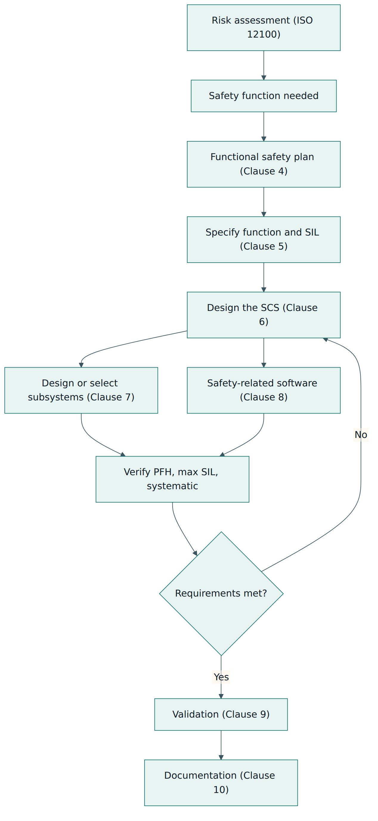
The 2021 edition is organised so that its clauses follow the order in which a designer actually works on a safety function. After the usual scope, references and terms (Clauses 1 to 3), the requirements run as follows. This is a paraphrased map, not the text of the standard.
- Clause 4 – Design process and management of functional safety – The overall design flow, the functional safety plan, configuration management and the handling of modifications. The plan names the activities, responsibilities, competences and documents for the whole job.
- Clause 5 – Specification of a safety function – How to turn the outcome of the risk assessment into a safety requirements specification: what the function must do, in which operating modes, how fast, how it reacts to faults, and the SIL it needs.
- Clause 6 – Design of an SCS – How to break the safety function into subsystems, choose an architecture, estimate PFH, consider systematic integrity and electromagnetic immunity, handle parametrization, refer to security and plan periodic testing.
- Clause 7 – Design and development of a subsystem – Requirements for subsystems you build from simpler elements, including architectural constraints, the basic subsystem architectures with their calculation methods, fault exclusions, diagnostics and the "maximum SIL" a subsystem can reach.
- Clause 8 – Software – Use cases for safety-related software, from configuring pre-assessed function blocks in a limited-variability language to writing full-variability code, with requirements scaled to each, including independence for software verification.
- Clause 9 – Validation – Planning and performing validation by analysis and testing, including fault injection, with independence requirements.
- Clause 10 – Documentation – What must be recorded and handed over so the SCS can be used, maintained and modified safely.
Informative annexes support the clauses. They include a method for determining the required SIL from a risk estimate (Annex A), a worked example of the design method for a guard-door function (Annex B), example MTTFD and B10D values for components (Annex C), estimates of diagnostic coverage (Annex D), a scoring method for susceptibility to common cause failures (Annex E), a guideline for software level 1 (Annex F), examples of safety functions (Annex G), simplified methods for estimating subsystem PFH (Annex H), an example functional safety plan (Annex I) and the minimum independence for reviews, verification and validation (Annex J). "Informative" means the annexes guide and illustrate rather than impose requirements, but in practice most users rely on them.
Reading the structure as a beginner
Two features of this structure are worth noticing. First, the loop in Figure 1: design and verification iterate until the subsystems together meet both the numerical target and the qualitative requirements. Second, the standard starts after the risk assessment. It assumes ISO 12100 has been applied to identify hazards, and that the designers have decided a control function is the right risk reduction measure. If the risk assessment is weak, a perfectly executed IEC 62061 design will protect against the wrong things.
Requirements in two dimensions
Throughout Clauses 6 and 7, a subsystem must satisfy several conditions at the same time. Its PFH must be low enough. Its architecture (fault tolerance plus diagnostics, expressed through architectural constraints) must permit the SIL. Its systematic capability, meaning the quality of how it was developed and how it is applied, must match. And the design must address common cause failures. A useful habit is to keep a short checklist per subsystem with one line for each condition; whichever condition is weakest sets the subsystem's maximum SIL.
Lesson 4 – How it works in practice
Step 1: plan the work
The 2021 edition makes a functional safety plan explicit. For a single machine it may be a few pages; for a large line it is a controlled project document. It identifies the safety functions in scope, who does what, the competence required, which documents will be produced, how design reviews, verification and validation will be performed and by whom, and how changes will be controlled. Configuration management, knowing exactly which versions of hardware, software and parameters make up the SCS, belongs here too, because a validated safety function is only valid for the configuration that was validated.
Step 2: specify each safety function
A safety requirements specification describes each safety function in two parts. The functional part says what happens: the trigger (guard opened, light curtain interrupted, enabling switch released), the response (remove torque, close a valve, limit speed), the required response time, the operating modes in which the function is active, priorities against other functions, the frequency of operation, environmental conditions, and the reaction to detected faults. The integrity part states the required SIL. A good specification also lists assumptions, such as how far the guard is from the hazard and how long the machine takes to stop, because those link the safety function to the physical layout.
Step 3: assign the required SIL
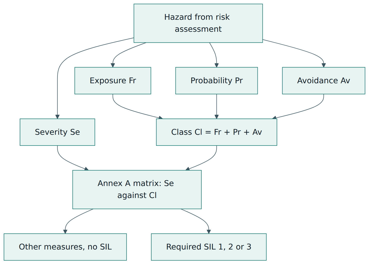
Annex A gives a widely used method. For each hazard that the safety function protects against, the team estimates four parameters, each on a small integer scale defined in the annex:
- Severity of the possible harm (Se), from reversible injuries needing first aid up to irreversible injury or death.
- Frequency and duration of exposure of persons to the hazard (Fr).
- Probability that the hazardous event occurs (Pr), considering the machine's behaviour and human behaviour.
- Possibility of avoiding or limiting the harm (Av), for example whether the motion is slow enough to react to.
The last three scores are added to give a class (Cl). The SIL is then read from a matrix with severity on one axis and class on the other. Low combinations need no SIL and are handled by other measures; higher combinations call for SIL 1, 2 or 3. The method is deliberately coarse. Its value lies in forcing an explicit, recorded discussion of each factor, so reviewers can see why a team chose SIL 2 rather than SIL 1. Teams should estimate the risk without the safety function being assessed, otherwise they double-count its benefit.
Step 4: decompose into subsystems
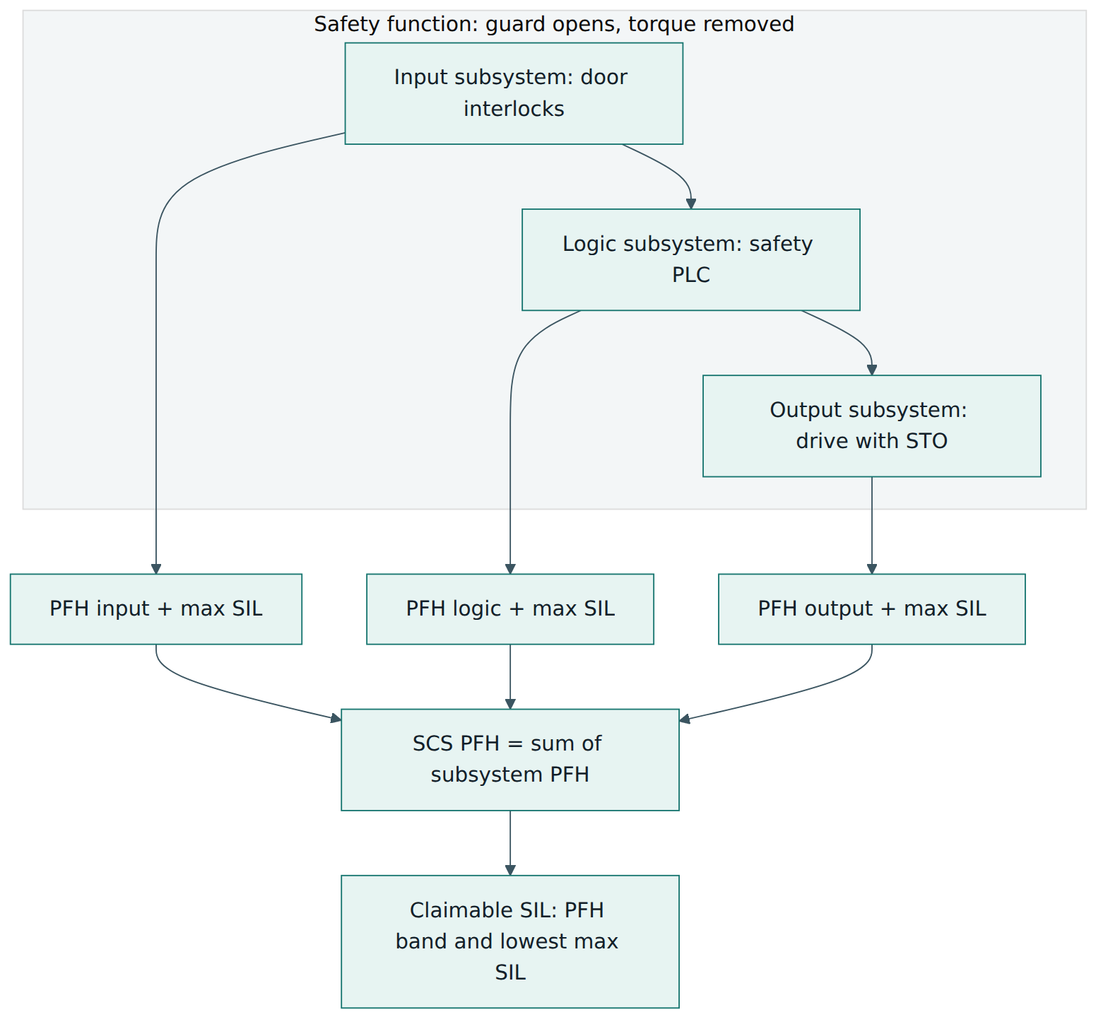
Every safety function is broken down into function blocks, which are realised by subsystems. The classic chain is detect (input subsystem), decide (logic subsystem), act (output subsystem), but real functions may have several input or output subsystems, for example two drives that must both remove torque. Because all subsystems in the chain must work for the function to work, the PFH of the SCS is, to a good approximation, the sum of the subsystem PFH values. The SIL the SCS can claim is also limited by the lowest maximum SIL among its subsystems, and by the systematic capability of all parts. If any one subsystem is only good for SIL 1, the whole function is at most SIL 1, however good the rest is. Communication links between subsystems, such as a safety fieldbus, contribute their own small dangerous failure frequency and must be included.
Step 5: select pre-assessed subsystems or design your own
Many subsystems are bought as finished products whose manufacturer states the PFH, the maximum SIL and the conditions of use: safety PLCs, safety relays, light curtains, drives with safe torque off (STO). Using them is straightforward, provided you respect their manual: wiring, test intervals, mission time, ambient limits and the configuration rules on which the figures depend. Ignoring a single condition, such as wiring both channels through a single cable without protection, can invalidate the stated figures.
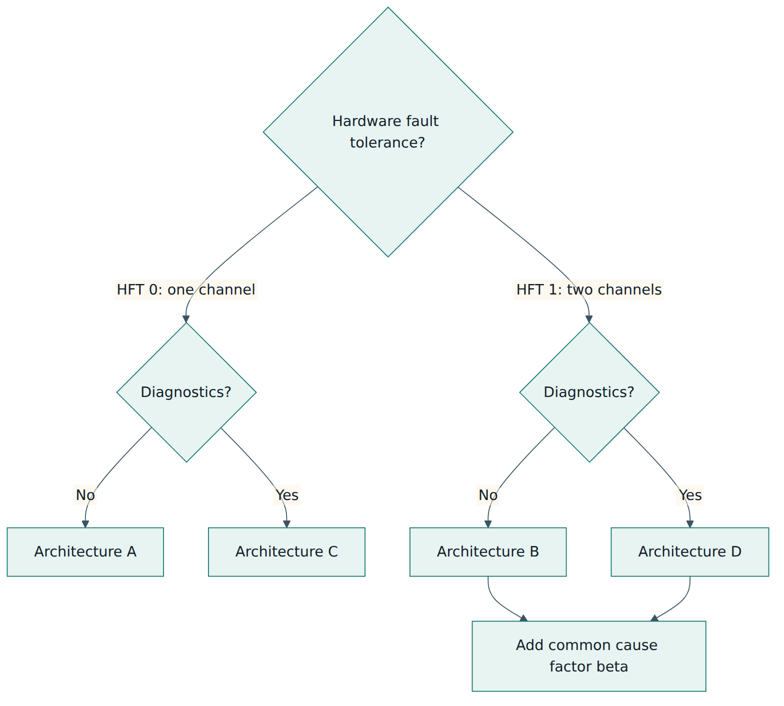
Where you build a subsystem from simpler elements, such as two standard interlock switches or two contactors, Clause 7 applies. You choose an architecture, gather reliability data for the elements, estimate diagnostic coverage and common cause susceptibility, and calculate PFH. The standard describes four basic subsystem architectures, labelled A to D, which are logical models, not wiring diagrams:
- Architecture A: single channel, no fault tolerance, no diagnostics. The dangerous failure rates of the elements simply add.
- Architecture B: two channels (fault tolerance of one) without diagnostics. A single fault is tolerated, but faults can accumulate unnoticed, so the proof test or mission time interval matters, and common cause failures must be considered.
- Architecture C: single channel with diagnostics. Detected faults lead to a safe reaction, so only undetected dangerous failures count; how fast the diagnostics react relative to demands matters.
- Architecture D: two channels with diagnostics. The most robust of the four, typical for SIL 2 and SIL 3 functions built from electromechanical parts.
Reliability data for electromechanical elements usually comes as a B10D value: the number of operations after which ten per cent of a population is expected to have failed dangerously. Combined with how often the device actually operates, it gives a dangerous failure rate. Electronic components come with failure rates from manufacturers or recognised data handbooks. Annex C offers typical values to use when no better data exists, but manufacturer data for the actual product should be preferred.
Alongside the PFH, architectural constraints link hardware fault tolerance and safe failure fraction to the highest SIL the subsystem can claim. In essence, a single-channel subsystem needs a very high share of safe or detected failures to reach a high SIL, while a two-channel subsystem reaches the same SIL with less. For example, the first edition already showed that a single-fault-tolerant subsystem with an SFF of 75 % is limited to SIL 2 regardless of its PFH. The constraints exist because a low calculated PFH can hide a fragile structure built on optimistic data.
Common cause failures are handled with a beta factor: the fraction of failures assumed to hit both channels at once. A scoring checklist in Annex E awards points for measures such as physical separation, diversity of technology, overvoltage protection, environmental testing and competence of the designers; the score translates into a beta value used in the formulas. Good separation and diversity therefore directly lower the calculated PFH.
Step 6: software and parametrization
Most machinery safety functions today involve a programmable logic subsystem. Clause 8 distinguishes use cases. The simplest is configuring or programming a pre-assessed safety PLC with a limited variability language (LVL), such as function block diagrams or ladder logic made of certified safety blocks; the standard calls the corresponding level of rigour software level 1, with requirements focused on specification, structured design, reviews, testing and version control. Writing application code in a full variability language (FVL), such as C, calls for the more demanding software level 2, a fuller V-model lifecycle that adds steps such as software system design and software integration testing. Annex F gives guidance for level 1. Embedded software inside complex devices such as the safety PLC itself is the device manufacturer's job under IEC 61508-3. The 2021 edition also requires a degree of independence for software verification: someone other than the author must check the work, with the required independence depending on SIL and use case.
Parametrization gets its own requirements because so many safety devices are now configured rather than wired: safe speed limits, safe positions, scanner protective fields, muting conditions. Parameters must be specified, protected against unauthorised or accidental change, checked after transfer to the device (for example by reading back and comparing a checksum), documented with their versions and included in validation. A wrong scanner field is as dangerous as a broken wire.
Step 7: periodic testing and security
Some faults cannot be found by automatic diagnostics, especially in architectures without diagnostics or in elements that rarely change state. The 2021 edition added requirements on periodic testing: where the design depends on tests performed at intervals, by the system itself or by people, the test, its interval and who performs it must be defined, and the information for use must tell the user. The standard also requires the designer to consider security threats that could compromise safety functions, while referring to IEC TR 63074 for the specific measures, because a safety parameter that can be changed over an unprotected network is a safety problem.
Step 8: validate and document
Validation, in Clause 9, confirms that each safety function as built does what the specification says, at the required integrity, in the real machine. It combines analysis (reviewing the specification, calculations and design against the risk assessment) with testing: functional tests in every relevant operating mode, response time and stopping time measurements, and fault injection, deliberately disconnecting a channel, bridging a contact or simulating a stuck output to show that faults are detected and lead to a safe state. Validation is planned in advance and recorded, with the required independence. The documentation required by Clause 10 then captures the specification, design, calculations, software, parameters, test results and instructions for use and maintenance, so that anyone modifying the machine years later can understand what must not be broken.
Roles and artefacts at a glance
A typical project involves a safety function owner or functional safety manager who maintains the plan, controls designers who specify and design, a software developer, a verifier and validator with appropriate independence, and the customer or end user who supplies operating information and later performs periodic tests. Key artefacts are the risk assessment, the safety requirements specification, the SIL determination records, the subsystem calculations, the software and parameter records, the validation plan and report, and the information for use.
Lesson 5 – Assessment, certification and compliance
There is no "IEC 62061 certified company"
IEC 62061 is a design standard, not a management system standard. There is no accredited scheme that certifies an organisation as "IEC 62061 compliant" in the way ISO 9001 certifies a quality management system. Compliance is a property of a specific safety function on a specific machine, demonstrated by evidence in the technical documentation. The responsible party is normally the manufacturer who places the machine on the market or the organisation that substantially modifies it.
Three kinds of third-party involvement
- Component certification. Manufacturers of safety PLCs, relays, drives and sensors often have their products assessed by a certification body, which issues a certificate stating the standards applied, the maximum SIL and the conditions of use. Such certificates tell you what a component can contribute; they do not certify your machine.
- Project assessment. A machine builder or end user may ask an independent assessor to review a safety function design, calculations and validation, either to satisfy a customer, an insurer or a regulator, or as an internal quality step. The 61508 Association's CASS scheme publishes free assessment templates for IEC 62061 that some organisations use to structure such reviews.
- Personnel qualifications. Several certification bodies offer functional safety engineer programmes for machinery. They demonstrate an individual's knowledge; the standard requires competence but does not require any particular certificate.
Regulatory context
In the European Union, machinery must meet the essential health and safety requirements of the Machinery Directive 2006/42/EC, which the Machinery Regulation (EU) 2023/1230 replaces from 20 January 2027. Harmonised standards whose references are cited in the Official Journal give a presumption of conformity with the requirements they cover. EN IEC 62061 is the European adoption of the standard; manufacturers should check the current citation list and any restrictions noted in it before relying on a presumption of conformity. Outside Europe, IEC 62061 is used as recognised good engineering practice, frequently specified by large buyers such as automotive manufacturers in their machine purchasing standards.
What an assessor actually looks for
Whether the reviewer is a customer, an independent assessor or your own safety team, the questions are similar:
- Is there a recorded risk assessment, and does each safety function trace back to specific hazards?
- Is the required SIL justified with recorded parameters, and was risk estimated without the function under assessment?
- Does every subsystem meet the PFH, architectural constraint, systematic capability and common cause requirements, with data sources named?
- Are component manuals' conditions of use respected in the actual wiring, configuration and test intervals?
- Was software developed and verified at the right level with the required independence, and are versions and checksums recorded?
- Does the validation report show fault injection and response time tests, not just "it stops when I open the door"?
- Is there a process for controlling modifications and repeating validation after changes?
A claim of "SIL 2" without this evidence is only an assertion.
Lesson 6 – Worked example
The situation
A mid-sized manufacturer, here called NorthLine Packaging, builds a case-packing machine. Operators open a hinged guard door several times per hour to clear jammed cartons. Behind the door a servo-driven pusher moves fast enough to crush a hand. The design team decides to apply IEC 62061 because the machine uses a safety PLC and safety drives, and their main customer's specification names it. The figures below are illustrative, chosen to show the method; a real project uses the actual data of the selected products.
1. Plan and risk assessment
The functional safety manager writes a short functional safety plan: three safety functions (guard door, emergency stop, safe speed during setup), named designers, a verifier from another team, a validation plan, and configuration management for the safety PLC program and drive parameters. The ISO 12100 risk assessment identifies crushing by the pusher during jam clearing as the main hazard. A fixed guard is impossible because operators need access, so an interlocked movable guard with a safety function is chosen.
2. Specify the safety function
The team writes: "When the guard door is opened in any operating mode, remove torque from the pusher drive within the response time set by the stopping performance; prevent restart until the door is closed and a reset is given outside the guarded area. On detection of a fault in the function, keep torque removed and indicate the fault." They record the frequency of door opening, the environment (dusty, 5–40 °C) and the distance between door and pusher.
3. Determine the required SIL
Using Annex A, the team assesses the hazard without the interlock. A crush injury to the hand could cause permanent loss of fingers, so severity is high but not fatal. Exposure is frequent, short and repeated many times per shift; the probability of the hazardous event is judged likely because jams invite people to reach in quickly; avoidance is judged impossible because the pusher moves faster than a person can withdraw. They score each parameter, add the three class parameters, read the matrix, and document the result: SIL 2 required. Their reasoning for each score is written down so that a reviewer can challenge it; a one-point change in exposure or probability could move the result to the next SIL, which is exactly why the record matters.
4. Decompose and select subsystems
The team splits the function into three subsystems:
- Input: two interlock switches on the door, one with a direct-opening contact and one of a different type, wired as two channels to the safety PLC. This is a self-built subsystem, so Clause 7 applies; they model it as architecture D because the PLC compares the two channels and detects discrepancies.
- Logic: a certified safety PLC whose manual states a maximum SIL of 3 and a PFH of around 1 × 10⁻⁹ per hour for the configuration used.
- Output: the servo drive's safe torque off function, certified with a maximum SIL of 3 and a PFH of around 1 × 10⁻⁸ per hour, wired as the manual requires.
5. Calculate and check
For the switches, the team takes the manufacturer's B10D values and the expected number of door operations per year to derive dangerous failure rates. They score common cause measures (separate mounting, different switch types, protected cable routing, components rated for the environment) and get a beta factor in the low range. Diagnostic coverage comes from the PLC's cross-monitoring of the two channels, checked at every door opening. With these inputs the architecture D formula gives a PFH of a few times 10⁻⁹ per hour, and the architectural constraints allow SIL 3 for this subsystem.
Adding the subsystems, roughly 3 × 10⁻⁹ + 1 × 10⁻⁹ + 1 × 10⁻⁸, gives about 1.4 × 10⁻⁸ per hour. That lies inside the SIL 3 band and well below the SIL 2 limit of 10⁻⁶. Every subsystem's maximum SIL is at least 2, so the function can claim SIL 2 with margin. The team records data sources, assumptions and the calculation in the technical file. A verifier from another team checks the arithmetic and the assumptions, especially the number of door operations, which drives the switch failure rate.
6. Software and parameters
The safety PLC program is written in a limited variability language using the manufacturer's certified function blocks for dual-channel monitoring and reset, so the team applies the software level 1 approach: a software specification derived from the safety requirements, a structured program separated from the standard machine logic, a review by a colleague who did not write it, testing of each function block's behaviour including faults, and version control with the program's checksum recorded. The drive's STO needs no parameters, but the setup-speed function uses a safe speed limit in the drive, so the parameter set is specified, password-protected, read back and compared after download, and documented with its checksum.
7. Validate
The validation plan lists tests for every operating mode. The validator, a different engineer, opens the door during automatic cycle, during manual jog and during a reset, and measures the time until the pusher stops. They inject faults: disconnecting one switch channel, bridging one channel, removing the STO feedback, and confirming each time that the fault is detected, the pusher stays without torque and restart is prevented. Two findings appear: the reset button can be reached from inside the guarded area, and the stopping time at maximum speed is longer than the guard distance assumed. The team moves the reset button and limits maximum speed, updates the documents, and repeats the affected tests.
8. Hand over and maintain
The information for use explains the safety functions, the required periodic checks (for example functional testing of the door interlock at defined intervals where automatic diagnostics need a state change to detect faults), the meaning of fault indications, and the rule that any change to safety wiring, program or parameters requires re-verification and re-validation. Two years later, when the customer asks for a faster pusher, the change request triggers an impact analysis, a new stopping-time measurement and repeated validation of the guard function. The technical file makes this a day's work instead of a guessing game.
Lesson 7 – Relationship to other standards and frameworks
IEC 62061 sits in a family. The table below shows how it relates to the standards you are most likely to meet alongside it.
| Standard | What it covers | Relationship to IEC 62061 |
|---|---|---|
| IEC 61508 | Generic functional safety of electrical, electronic and programmable electronic systems, SIL 1 to 4, all sectors | Parent framework. IEC 62061 is its machinery sector standard; complex devices such as safety PLCs are developed to IEC 61508 and then used as subsystems. |
| ISO 13849-1 | Safety-related parts of machine control systems, expressed as performance levels PL a to e with categories B and 1 to 4 | The other machinery functional safety standard. Similar goal, different method; subsystems designed to one can be integrated into a function designed to the other. |
| ISO 12100 | General principles for machine design, risk assessment and risk reduction | Comes first: its risk assessment identifies the hazards and decides where a safety function is needed. |
| IEC 60204-1 | Electrical equipment of machines, including protection against electric shock and stop categories | Covers electrical hazards that IEC 62061 excludes and defines stop categories used when specifying stopping functions. |
| IEC 61800-5-2 | Functional safety of adjustable speed power drive systems, defining functions such as safe torque off and safe speed | Drive manufacturers use it; integrators use the resulting drives as output subsystems. |
| IEC 61511 | Safety instrumented systems in the process industry | Sister sector standard under IEC 61508; relevant where machinery sits inside a process plant. |
| IEC TR 63074 and IEC 62443 | Security aspects related to functional safety of machinery, and industrial automation security in general | Where IEC 62061 sends you for the security measures that protect safety functions from manipulation. |
IEC 62061 or ISO 13849-1?
Both standards aim at the same outcome: a safety function reliable enough for the risk. ISO 13849-1 (current edition 2023) uses performance levels and a simplified method based on designated architectures (categories), mean time to dangerous failure, diagnostic coverage and common cause scoring. It is popular for functions built mainly from simple electromechanical, hydraulic and pneumatic parts, and is supported by free calculation tools such as IFA's SISTEMA. IEC 62061 uses SILs and a more general subsystem approach, and it handles complex programmable systems and software in more depth. Now that the 2021 edition also covers non-electrical technologies, the choice is less about technology and more about the team's background, the customer's requirement and the complexity of the function.
The two are designed to work together. In terms of dangerous failure frequency, PL e corresponds to SIL 3, PL d to SIL 2, and PL b and c both correspond to SIL 1; PL a has no SIL equivalent. A subsystem documented with a PL and a PFH, such as a pneumatic valve assembly designed to ISO 13849-1, can be used as a subsystem inside an IEC 62061 safety function, and vice versa, provided the integration rules of the receiving standard are followed. What you should not do is mix the methods within one subsystem calculation without understanding both.
Common pitfalls and best practices
Common pitfalls
- Treating a certified component as a certified function. A SIL 3 safety PLC does not make a safety function SIL 3; the sensors, actuators, wiring, software and validation decide that.
- Skipping or rushing the risk assessment. Jumping straight to "we need SIL 2 everywhere" wastes money on some functions and under-protects others.
- Optimistic data. Using generic failure rates, ignoring the real number of operations per year, or assuming diagnostic coverage that the wiring does not provide.
- Forgetting common cause. Two channels in the same cable, the same switch type in the same dusty spot, the same software in both channels: redundancy on paper, single point of failure in reality.
- Validation by normal operation only. Showing that the machine stops when the door opens proves nothing about how it behaves with a fault present.
- Unmanaged changes. Changing a scanner field, a speed limit or a line of safety code after commissioning without re-verification and re-validation.
- Ignoring manual conditions. Test intervals, mission time, ambient limits and wiring rules in component manuals are part of the PFH claim.
Best practices
- Write the safety requirements specification before buying hardware. It drives every later decision and is the reference for validation.
- Record the reasoning for each SIL decision, including the parameter scores and the people involved, so reviewers can follow it.
- Prefer pre-assessed subsystems and certified function blocks where they fit; they reduce both calculation effort and systematic risk.
- Design in separation and diversity for redundant channels and score common cause honestly.
- Plan validation early, including fault injection and stopping-time measurements, and use a validator who did not design the function.
- Put software and parameters under version control with checksums, and protect them against unauthorised change.
- Define periodic tests and modification rules in the information for use, so the end user can keep the function at its integrity level.
Summary and key takeaways
- IEC 62061:2021 (Edition 2.0, amended in 2024 and 2026) is the machinery sector standard for functional safety within the IEC 61508 framework.
- It applies to safety-related control systems of non-hand-held machines and, since 2021, to non-electrical technologies as well as electrical ones.
- Each safety function gets a specification and a required SIL (1 to 3), often determined with the Annex A severity and class matrix.
- A safety function is realised by subsystems; their PFH values add up, and the lowest maximum SIL among them caps the result.
- Random failures are addressed with architecture, diagnostics, reliability data and common cause measures; systematic failures with planning, software discipline, independence and validation.
- The 2021 edition introduced a functional safety plan, expanded parametrization requirements and added requirements for periodic testing, software use cases and independence.
- There is no organisational certificate: compliance is shown per machine through a traceable technical file, supported by certified components where used.
- ISO 13849-1 pursues the same goal with performance levels; the two standards can be combined at subsystem level.
Reflection questions
- Pick a machine you know. Which of its protective measures are safety functions in the sense of IEC 62061, and which are purely physical safeguards?
- For one hazard on that machine, how would you score severity, exposure, probability and avoidance, and where would you expect your colleagues to disagree?
- If a supplier offers a light curtain certified for SIL 3, what further information would you need before claiming a SIL for the safety function that uses it?
- How would you design a two-channel interlock so that a single environmental cause is unlikely to defeat both channels?
- Your plant wants to raise the speed of an existing machine. Which documents and tests from the original IEC 62061 work would you revisit, and in what order?
Further reading and official sources
- IEC 62061:2021 – Safety of machinery – Functional safety of safety-related control systems – International Electrotechnical Commission (IEC webstore)
- IEC 62061:2021+AMD1:2024 consolidated version – IEC webstore
- IEC 62061:2021/AMD2:2026 – Amendment 2 – IEC webstore
- What is IEC 62061? – The 61508 Association
- Regulation (EU) 2023/1230 on machinery – EUR-Lex, European Union
- SISTEMA software for ISO 13849-1 – Institute for Occupational Safety and Health of the DGUV (IFA)
Original tutorial by xOps School (DevOpsSchool Private Limited), written from public sources about IEC 62061. Not affiliated with or endorsed by the standard's owner; standard names are trademarks of their owners. Buy the official standard from its publisher for the authoritative text.