
SAE ARP4761A – Tutorial (about 60 minutes)
- View
SAE ARP4761A is the aerospace industry's recommended practice for carrying out the safety assessment of civil aircraft, their systems and their equipment. Aircraft manufacturers, system suppliers, safety engineers and certification specialists use it to find out what can go wrong with aircraft functions, how severe each outcome would be and whether the design makes the dangerous outcomes rare enough. After this tutorial you will be able to explain the safety assessment process it describes, read and challenge the main analyses, and see how they feed development assurance and certification.
Course overview
Edition and status: the current edition is SAE ARP4761A, Guidelines for Conducting the Safety Assessment Process on Civil Aircraft, Systems, and Equipment, issued by SAE International (committee S-18) in December 2023. It is Revision A of ARP4761, first published in 1996, which it supersedes. It was released together with its European twin, EUROCAE ED-135 (Working Group WG-63, December 2023), and together with the companion development guideline ARP4754B / ED-79B. No later revision had been announced when this course was checked. Note that aviation authorities' advisory material, such as FAA AC 25.1309-1B (August 2024), refers to "ARP 4761" generically, so agree with your authority which revision your certification project uses — verified 2026-10-29.
Who it is for: systems engineers, safety and reliability engineers, avionics and hardware engineers, software leads, certification and airworthiness staff, project managers, and people joining aerospace from automotive, rail, medical devices, energy or defence. It also suits teams in drone and advanced air mobility start-ups who meet aircraft safety assessment for the first time.
Prerequisites: none. A basic idea of what a system architecture is and some comfort with probabilities written as powers of ten will help. Every aviation and safety term is explained the first time it appears.
By the end of this tutorial:
- You will be able to explain why aircraft need a structured safety assessment and what ARP4761A does and does not cover.
- You will be able to define the core vocabulary: failure condition, severity classification, average probability per flight hour, latent failure, exposure time, independence, functional failure set and development assurance level.
- You will be able to describe the six assessment steps (AFHA, PASA, SFHA, PSSA, SSA and ASA) and the analysis methods that support them.
- You will be able to follow how safety requirements flow down a design and how evidence flows back up to show they are met.
- You will be able to explain how the safety assessment is reviewed by aviation authorities and what "compliance" means for a recommended practice.
- You will be able to apply the process to a realistic system and spot the decisions that drive risk and cost.
- You will be able to place ARP4761A next to ARP4754B, DO-178C, DO-254, DO-326A, ISO 26262 and IEC 61508.
Lesson 1 – Origins, purpose and scope
Why aircraft need a formal safety assessment
An airliner is a collection of tightly connected systems: flight controls, engines and their controls, hydraulics, electrical power, fuel, landing gear and brakes, cabin pressure, navigation, displays and many more. Each one can fail in several ways, and failures can combine. A leak in one hydraulic circuit is a nuisance on its own; the same leak during a take-off with an engine failure and a dormant fault in a backup pump could be something much worse.
Aviation regulations do not try to list every possible failure. Instead they set a general rule. For large aeroplanes, the US rule 14 CFR 25.1309 and the European certification specification CS 25.1309 say, in essence, that systems must perform their intended function and that the more severe the effect of a failure, the less likely it must be. A failure that could cause the loss of the aircraft must be extremely improbable and must not result from any single failure. A failure with milder effects may be more frequent. This is often drawn as an inverse relationship between severity and probability: the worse the outcome, the rarer it must be.
A rule written in this way leaves a hard question for the manufacturer: how do you show, with evidence an authority can review, that every relevant failure has been found, judged correctly and made rare enough? ARP4761A answers that question. It describes a structured safety assessment process and a toolbox of analysis methods that the industry has refined over decades and that authorities recognise as valid when they are applied correctly.
A short history
SAE International is a global standards body for the automotive and aerospace industries. Its Aerospace Recommended Practices (ARPs) capture accepted engineering practice. ARP4761 was published in 1996 by the SAE committee S-18, in the same year as ARP4754, which covers how aircraft systems are developed. For almost three decades ARP4761 was the reference for fault tree analysis, failure modes and effects analysis, functional hazard assessment and common cause analysis on civil aircraft, and its worked example of a wheel brake system became a classic teaching case in safety engineering.
Aircraft changed a great deal after 1996. Systems became highly integrated, sharing computers, networks and power sources; software took over functions once done mechanically; and model-based engineering tools appeared. After more than a decade of committee work, SAE issued Revision A in December 2023. EUROCAE, the European organisation that develops aviation industry standards, issued the technically equivalent ED-135 at the same time. The companion development guideline was revised to ARP4754B / ED-79B in the same month, and the two documents were deliberately aligned.
What changed in Revision A
- The aircraft level is now covered from start to finish: besides the aircraft-level FHA, which the 1996 edition already had, there is a Preliminary Aircraft Safety Assessment and a final Aircraft Safety Assessment alongside the system-level steps.
- The detailed activities for assigning development assurance levels are described in ARP4761A, while ARP4754B keeps the general principles.
- New methods are described: Model-Based Safety Analysis, in which failure behaviour is derived from a model of the system, and Cascading Effects Analysis, which follows how a failure in one system propagates into others.
- The established methods of the 1996 edition (fault trees, dependence diagrams, Markov analysis, FMEA and FMES, and the zonal, particular risk and common mode analyses) remain part of the toolbox.
What ARP4761A covers, and what it does not
ARP4761A covers the safety assessment of civil aircraft, their systems and their equipment during development, with the main focus on showing compliance with the 1309-type rules for large aeroplanes. Its methods are also widely used for small aeroplanes, rotorcraft, engines and new aircraft types, where the rules have the same severity-versus-probability idea but sometimes different numerical targets.
It does not tell you how to develop the system (that is ARP4754B), how to develop software (DO-178C) or complex electronic hardware (DO-254), how to protect the aircraft against intentional unauthorised electronic interaction (the DO-326A family), or how to manage safety in airline operations (a safety management system). It also does not set the numerical targets: those come from the regulations and their advisory material. ARP4761A provides the methods; the authority's rules set the bar.
Guidance, not law
Like other ARPs, ARP4761A is not a regulation. Authorities publish advisory material, for example FAA Advisory Circular AC 25.1309-1B and the EASA Acceptable Means of Compliance AMC 25.1309, which describe acceptable ways of showing compliance and point to the ARP4761 methods. An applicant may propose another method, but in practice almost every civil programme uses ARP4761 or ARP4761A because authorities, suppliers and engineers all understand it.
Lesson 2 – Key concepts and vocabulary
Safety assessment has its own language. These terms appear throughout ARP4761A and the related regulations; the definitions below are paraphrased.
- Function – something the aircraft or a system does, described independently of how it is implemented, for example "decelerate the aircraft on the ground" or "display attitude to the crew".
- Failure condition – a condition that affects the aircraft or its occupants, caused or contributed to by one or more failures or errors, taking into account the flight phase and the operating or environmental conditions. "Loss of all wheel braking during landing roll" is a failure condition; "brake valve stuck closed" is a failure that may contribute to it.
- Severity classification – the grading of a failure condition by its worst credible effect: No Safety Effect, Minor, Major, Hazardous or Catastrophic. The definitions come from the regulations and their advisory material.
- Average probability per flight hour – the expected number of occurrences of a failure condition over the life of the whole fleet divided by the total flight hours of that fleet. It is usually calculated for a flight of average duration and then divided by that duration.
- Safety objective – the maximum average probability allowed for a failure condition given its severity, plus qualitative objectives such as "no single failure may lead to a catastrophic failure condition".
- Latent failure – a failure that is present but not detected or announced, so it can sit unnoticed until a second failure turns it into a problem. A backup pump that has quietly failed is a typical latent failure.
- Exposure time – the period during which a latent failure can remain undetected, usually set by the interval between checks. Longer exposure means a higher chance that the second failure arrives while the first one is still present.
- Independence – the property that two items or failures cannot be caused by the same event. Many safety arguments multiply probabilities of two failures, which is only valid if they are independent.
- Common cause – a single event, error or condition that defeats more than one part of the design at once, such as a fire, a shared power supply, the same software error in two channels or a maintenance mistake.
- Functional Failure Set (FFS) – a group of members (functions or items) whose failures together produce a failure condition. It is the basis for assigning development assurance levels when the design relies on more than one independent member.
- Development Assurance Level (DAL) – the level of rigour, from A (most) to E (none), applied to the development of a function (FDAL) or an item such as software or hardware (IDAL). It addresses errors in requirements, design and implementation, which cannot be credibly quantified.
- Safety requirement – a requirement that comes out of the safety assessment, such as a probability budget, an independence demand, a monitor, a crew alert or a maintenance check.
- Certification Maintenance Requirement (CMR) – a mandatory scheduled maintenance task set during type certification, typically to find latent failures within a defined interval so that the safety objectives are still met.
- Safety assessment process – the whole set of assessments in ARP4761A, from the first aircraft-level hazard assessment to the final aircraft-level safety assessment, as opposed to a single analysis method.
Severity and probability work together
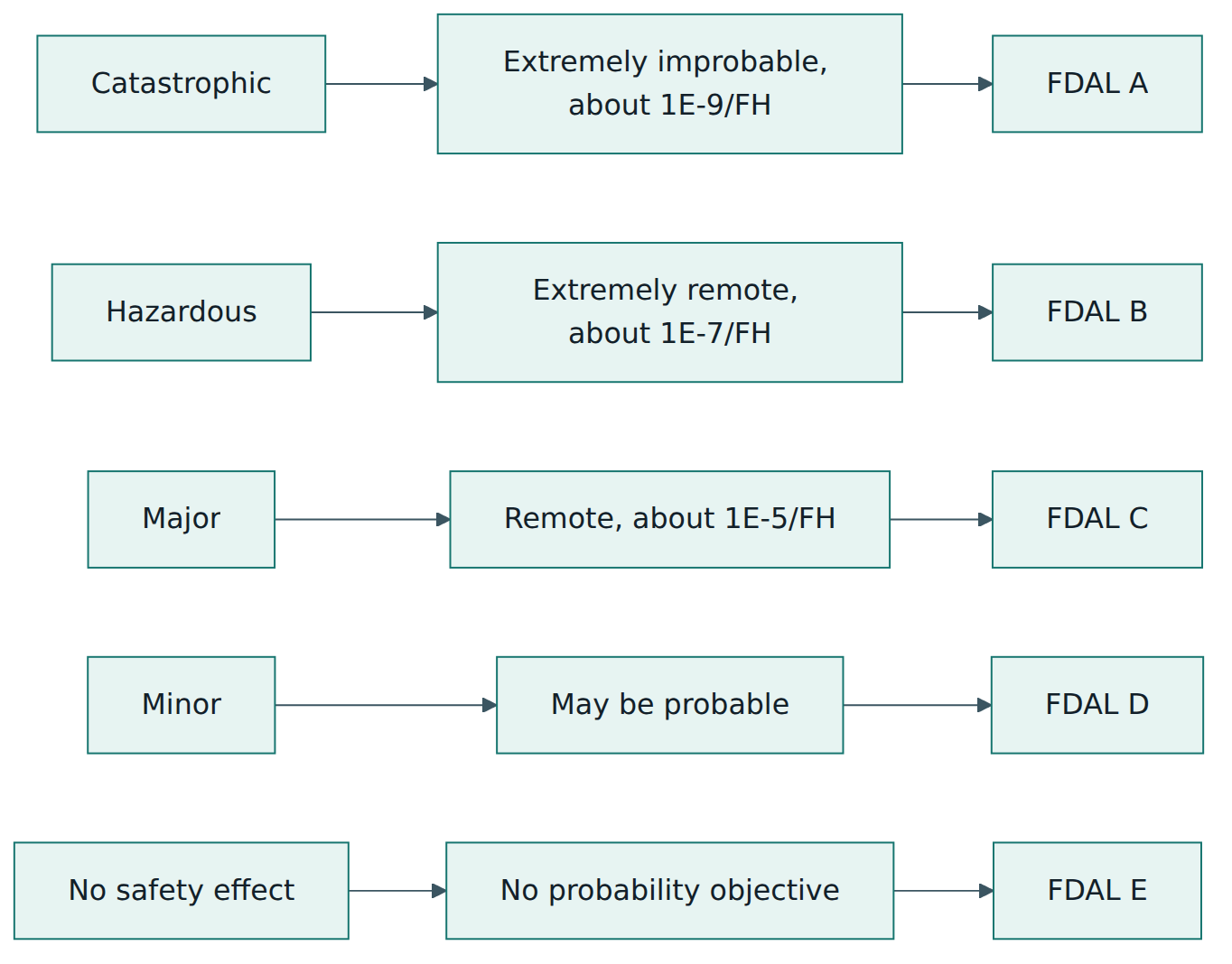
The heart of the approach is a matrix of severity against probability. The regulations and advisory material define qualitative probability terms: Probable, Remote, Extremely Remote and Extremely Improbable. For large aeroplanes, FAA AC 25.1309-1B gives them numerical ranges per flight hour: roughly 1E-3 to 1E-5 for Probable, 1E-5 to 1E-7 for Remote, 1E-7 to 1E-9 for Extremely Remote, and 1E-9 or less for Extremely Improbable. A Minor failure condition may be Probable; a Major one must be no more frequent than Remote; a Hazardous one no more frequent than Extremely Remote; and a Catastrophic one must be Extremely Improbable and must not result from a single failure.
The same severity drives the development assurance level. A function whose failure could be Catastrophic is developed at FDAL A, Hazardous at B, Major at C, Minor at D and No Safety Effect at E, unless the architecture provides independent members that allow some of them to be developed at a lower level, as explained in Lesson 4.
Two kinds of problem: random failures and errors
Beginners should notice that safety assessment deals with two different kinds of problem. Random hardware failures, such as a pump wearing out or a capacitor breaking down, occur at rates that can be estimated from reliability data, so their contribution can be calculated. Development errors, such as a wrong requirement or a software bug, are built into every unit and cannot be given a credible failure rate. ARP4761A therefore combines quantitative analysis for random failures with development assurance levels for errors. A fault tree that shows 1E-10 per flight hour says nothing about a requirement mistake that is present in both redundant computers.
Lesson 3 – Structure of the standard
ARP4761A is a long document. Its main body describes the overall safety assessment process, the role of each assessment step and how the safety process interacts with the development process of ARP4754B. Appendices then describe each process step and each analysis method in detail, with examples. You can think of it as two layers: processes that say what must be established and when, and methods that are tools used inside the processes.
The six process steps
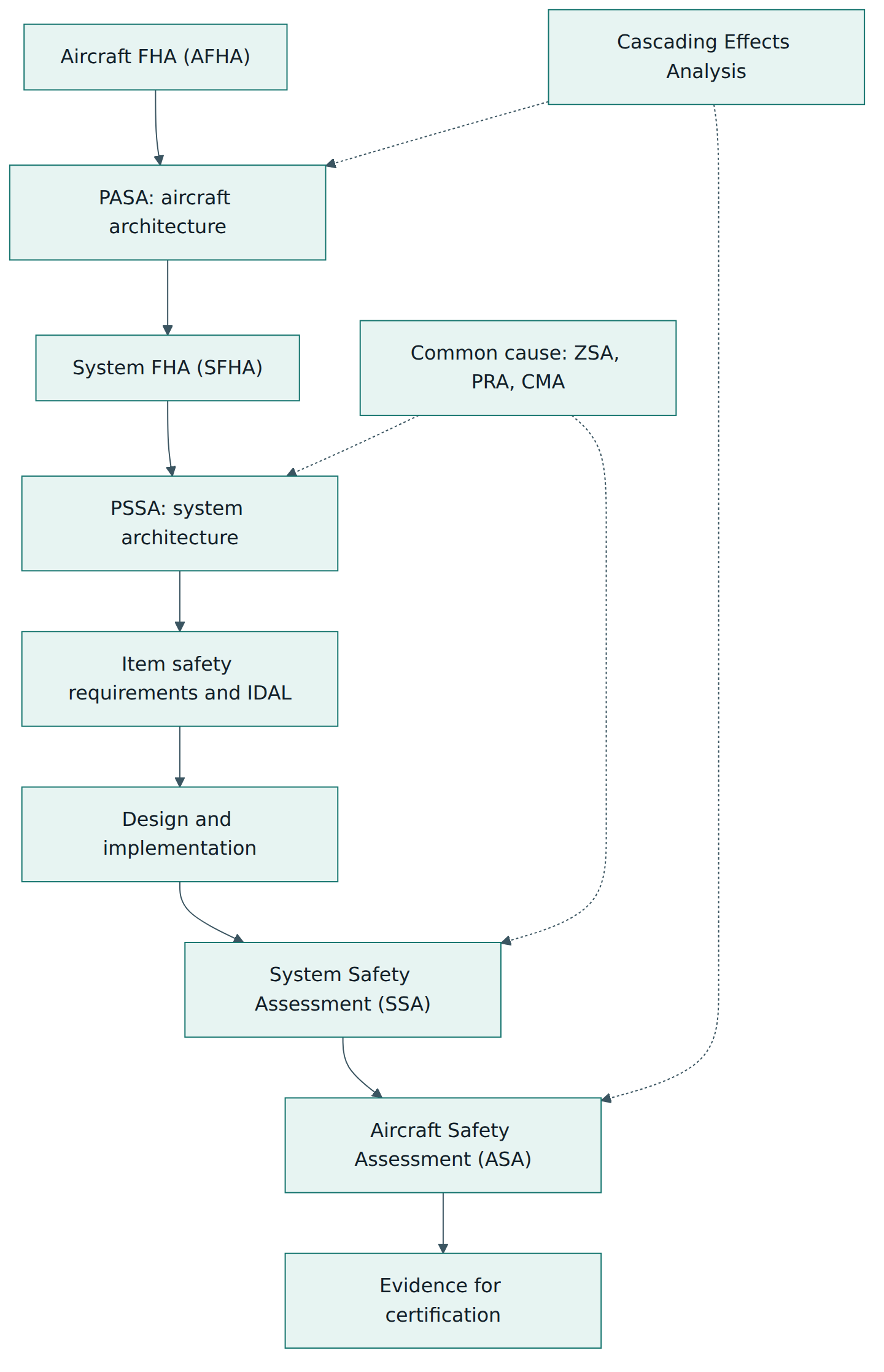
- Aircraft Functional Hazard Assessment (AFHA) – identifies the aircraft-level functions, the failure conditions associated with them and their severity classifications, early in the programme.
- Preliminary Aircraft Safety Assessment (PASA) – examines the proposed aircraft architecture, the way aircraft functions are allocated to systems and the interactions between systems, to derive aircraft-level safety requirements and check that the architecture can meet the objectives.
- System Functional Hazard Assessment (SFHA) – does the same as the AFHA for the functions of one system, linking its failure conditions to the aircraft-level ones.
- Preliminary System Safety Assessment (PSSA) – examines the proposed system architecture and derives safety requirements for the items (equipment, hardware, software) that make up the system, including probability budgets, independence needs and development assurance levels.
- System Safety Assessment (SSA) – a systematic evaluation of the implemented system showing that it meets its safety requirements and objectives, using the final design data.
- Aircraft Safety Assessment (ASA) – the aircraft-level evaluation that integrates the system results, checks combinations and cascading effects across systems and shows that the aircraft-level safety requirements and objectives are satisfied.
The analysis methods
The methods are grouped by what they are good at. ARP4761A presents them as tools; it does not demand that every method be used on every system.
- Fault Tree Analysis (FTA) – a top-down, deductive method. You start from an undesired event, such as a failure condition, and break it down through AND and OR gates into the combinations of lower-level failures that can cause it. It gives both the minimal combinations (cut sets) and, with failure rates, a probability.
- Dependence Diagram (DD) – a block-diagram view of the same logic, close to a reliability block diagram: series blocks mean any single failure breaks the path, parallel blocks mean all must fail.
- Markov Analysis (MA) – models the system as states and transitions, which suits repairable systems, reconfiguration and cases where the order of failures matters.
- Model-Based Safety Analysis (MBSA) – builds a model of the system that includes failure behaviour and generates results such as fault trees or failure combinations from it, keeping the analysis consistent with the evolving design.
- Failure Modes and Effects Analysis (FMEA) – a bottom-up, inductive method. For each component or function, you list how it can fail and what effect each failure mode has. The Failure Modes and Effects Summary (FMES) groups failure modes with the same effect so that their rates can feed the fault trees.
- Cascading Effects Analysis (CEA) – follows the effects of a failure in one system into the systems that depend on it, so that combined aircraft-level effects are not missed.
- Common cause analyses, often grouped as Common Cause Analysis (CCA): Zonal Safety Analysis (ZSA) checks the installation in each physical zone of the aircraft; Particular Risk Analysis (PRA) studies events outside the systems, such as fire, tyre burst, bird strike, lightning or uncontained rotor failure; Common Mode Analysis (CMA) checks that items assumed to be independent really are, considering shared design, software, manufacturing, maintenance and environment.
How the parts fit together
The process steps form a top-down then bottom-up pattern that mirrors the development process. On the way down, hazard assessments and preliminary assessments turn aircraft-level concerns into requirements on systems and items. On the way up, the system and aircraft safety assessments use the final design and the results of the analyses to show that those requirements are met. Common cause and cascading analyses run alongside both directions because independence and propagation must be considered from the first architecture sketch to the final installation.
Choosing qualitative or quantitative analysis
Not every failure condition needs a probability calculation. Minor failure conditions are usually handled with a qualitative argument, for example an FMEA or a design review showing that the system is simple and its failures are covered. Major failure conditions often need some analysis of the architecture, and Hazardous or Catastrophic failure conditions normally need full quantitative analysis supported by common cause analyses. The depth of analysis grows with severity, just as the development assurance level does.
Lesson 4 – How it works in practice
Step 1: start with functions, not equipment
The AFHA is performed very early, often when the aircraft is still a set of top-level requirements. The team lists aircraft functions (control flight path, control speed on the ground, provide breathable cabin air, communicate with air traffic control and so on). For each function, they consider failure conditions such as total loss, partial loss, unannunciated loss, and malfunction or erroneous operation, in each relevant flight phase. For each failure condition they record the effect on the aircraft, the crew and the occupants, the classification, the rationale and any assumptions, for example "crew is alerted and follows a procedure".
A good hazard assessment is a team activity. It needs systems engineers, test pilots or operational experts, human factors specialists and safety engineers, because the classification depends on how crews will notice and handle the condition. Assumptions about crew response are themselves safety-relevant and must later be validated, for example in a simulator.
Step 2: test the architecture early
The PASA and the PSSAs look at proposed architectures before they are frozen. Typical tools are preliminary fault trees or dependence diagrams for the most severe failure conditions. The questions are simple: does any single failure lead to a Catastrophic failure condition? Are there enough independent paths? Are the probability budgets achievable with realistic equipment? What must be monitored, alerted to the crew or checked during maintenance?
The outputs are requirements: probability budgets for items, requirements for independence or segregation, monitors and alerts, maintenance intervals, installation constraints and development assurance levels. These are passed into the development process of ARP4754B, where they are validated and later verified like any other requirement.
Step 3: assign development assurance levels
Development assurance levels start from the most severe failure condition a function can cause or contribute to. If a function can contribute to a Catastrophic failure condition on its own, it gets FDAL A. If the design relies on two or more independent members, the Functional Failure Set allows the levels to be shared. For a Catastrophic failure condition with two independent members, for example, the guidance allows options such as one member at level A and the other at a lower level, or both at level B. The trade only works if independence is demonstrated, which is why development assurance level assignment and common mode analysis are so tightly linked.
Function levels then flow to items. Software and hardware items receive IDALs that tell the DO-178C and DO-254 projects how much rigour to apply. ARP4761A now describes these assignment activities in detail, while ARP4754B keeps the general principles, so safety engineers and development engineers must work from the same functional failure sets.
Step 4: analyse the real design
As the design matures, the analyses are refined with real data. FMEAs are written for the equipment, using component failure rates from reliability data. The FMES summarises failure modes by effect and feeds the fault trees. The fault trees are updated with the final architecture, the final failure rates and realistic exposure times. Common cause analyses are completed: the ZSA is done on the real installation drawings or a digital mock-up, the PRA on the real routing of pipes, wires and equipment, and the CMA on the real design, suppliers and processes.
Step 5: close the loop at system and aircraft level
Each SSA checks every failure condition from the SFHA against its safety objective, confirms that every safety requirement from the PSSA has been met or explains how it was dispositioned, and lists the outputs that operators and maintainers need, such as CMRs, master minimum equipment list considerations and crew procedures. The ASA then integrates the system results, checks combinations of failures across systems and the cascading effects, and confirms that the aircraft-level objectives are met.
Latent failures and maintenance
Latent failures deserve special attention because they quietly erode redundancy. If a backup is only checked every 3,000 flight hours, then for much of that time the aircraft may be flying with no backup at all. Safety engineers reduce this risk by adding monitors that reveal failures to the crew, by power-up or periodic built-in tests, and by setting maintenance checks. Where a check is essential to meet a safety objective, it becomes a CMR. The 2024 revision of the FAA rule (amendment 25-152, August 2024) and AC 25.1309-1B added specific criteria for significant latent failures and for catastrophic combinations of two failures where either could be latent for more than one flight.
Roles and artefacts
| Role | Main contribution | Typical artefacts |
|---|---|---|
| Aircraft safety team (manufacturer) | Aircraft-level hazards, architecture, allocation, final integration | AFHA, PASA, ASA, CEA |
| System safety engineers | System hazards, architecture trades, safety requirements | SFHA, PSSA, SSA, fault trees, CMA |
| Equipment suppliers | Failure modes and rates of their equipment, item-level evidence | FMEA, FMES, reliability predictions |
| Installation and structures engineers | Physical segregation, zone checks, external threats | ZSA, PRA |
| Operations and maintenance specialists | Crew procedures, alerts, maintenance tasks | CMRs, procedure validation, MSG-3 inputs |
| Certification engineers | Agreement with the authority on methods and compliance | Certification plan, compliance reports |
Lesson 5 – Assessment, certification and compliance
What is actually certified
There is no ARP4761A certificate for a company, a product or a person. Authorities certify aircraft (through a type certificate), changes to them (through supplemental type certificates or major change approvals) and certain equipment (for example through technical standard order authorisations). The safety assessment is part of the evidence that the design complies with the relevant rules, typically 25.1309 and other system-specific requirements. Training courses may issue attendance certificates, but they are not regulatory approvals.
Agreeing the method
Early in a programme, the applicant describes in its certification plan which methods it will use to show compliance with each rule. For system safety, this usually means "the safety assessment process of ARP4761 or ARP4761A, together with ARP4754 or ARP4754B for development assurance". Because the advisory material refers to the documents without always naming a revision, applicants agree with their authority which revision applies, any deviations and any additional authority positions. FAA projects record such agreements in issue papers; EASA projects use certification review items. This is also where new methods such as MBSA or credit for particular independence arguments are discussed.
How the authority reviews the work
Authority engineers, or designees acting on their behalf, review the safety documents during the programme rather than only at the end. Typical review points are the AFHA and SFHAs, where classifications and assumptions are challenged; the PASA and PSSAs, where architecture choices and development assurance levels are agreed; and the SSAs and ASA, which form part of the compliance documentation. Reviewers look for complete coverage of functions and failure conditions, clear rationale for classifications, consistency between documents, validated assumptions, credible failure rate data, demonstrated independence and traceability of every safety requirement to its verification.
What "compliance" means here
Following ARP4761A does not by itself make a design compliant. The advisory material is explicit that meeting the numerical guidelines is some, but not necessarily sufficient, evidence. Authorities also expect sound engineering judgement, fail-safe design principles, qualitative arguments such as "no single failure is catastrophic", and test or simulator evidence where failure effects are uncertain. A fault tree with a good number but an untested assumption about crew reaction or about independence is a weak argument.
After certification
The safety assessment remains a living asset. Design changes, service experience, new failure data and incidents can invalidate assumptions, so manufacturers update the analyses for changes and use them in continued airworthiness work. CMRs and other maintenance outputs from the SSA become part of the instructions that keep the aircraft safe in service.
Lesson 6 – Worked example: a brake-by-wire system for a regional jet
This fictional example shows how the pieces connect. "Northwind Aero" is developing a new regional jet certified to large aeroplane rules. Its supplier, "Kestrel Systems", will provide an electrically controlled, hydraulically actuated wheel brake system. All numbers are illustrative.
Aircraft FHA
Northwind's aircraft safety team lists the function "decelerate the aircraft on the ground". Failure conditions include total loss of deceleration during landing, partial loss, asymmetric deceleration and uncommanded braking during take-off roll. With operational experts, they classify total loss of all deceleration means at high speed on landing as Catastrophic, because the aircraft could overrun the runway. Inadvertent full braking during the take-off roll is also judged severe. Each classification records its assumptions, such as runway conditions and which crew alerts are available.
PASA
The PASA allocates the deceleration function to three systems: wheel brakes, thrust reversers and ground spoilers. It notes that the brakes depend on hydraulic and electrical power, so the CEA must follow what happens to braking when a hydraulic or electrical system is lost. A requirement emerges: the brake system must keep an independent alternate mode that does not depend on the normal hydraulic circuit or the normal brake computer.
System FHA and PSSA
Kestrel performs the SFHA for the brake system and links its failure conditions to the aircraft ones. Its key failure condition, "loss of all wheel braking", contributes to the catastrophic aircraft-level condition. The proposed architecture has a normal channel (brake control unit 1, green hydraulic system, normal valves) and an alternate channel (brake control unit 2, blue hydraulic system with an accumulator, alternate valves). A preliminary fault tree is built.
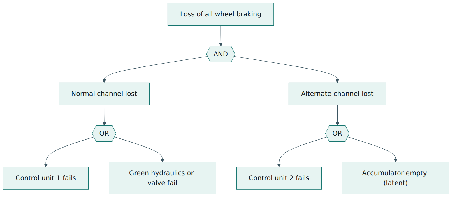
If each channel loses its function at about 1E-5 per flight hour and the two are independent and every failure is revealed at once, the combination looks comfortably below 1E-9. Kestrel's safety engineer, however, raises three questions. First, the accumulator could lose pressure without anyone noticing, so its exposure time could be long. Second, both brake control units were planned to run the same software on the same processor. Third, the hydraulic lines of both channels run through the same wheel well, which is exposed to tyre burst.
Turning questions into requirements
- Latent failure: a pressure sensor and a crew alert are added for accumulator pressure, and a periodic check is proposed as a CMR so the exposure time is bounded.
- Common mode: the CMA shows that identical software in both units is a common cause for which no failure rate can be given. The functional failure set analysis offers two options: develop the software in both units at IDAL A, or introduce a dissimilar, simpler alternate controller so the levels can be shared. Kestrel chooses a simple alternate controller with its own development and, after agreement on the approach, assigns levels using the functional failure set guidance.
- Particular risk: the PRA for tyre burst maps the debris zones and requires the alternate hydraulic line to be routed outside the most exposed areas, with physical separation from the normal line.
- Zonal checks: the ZSA of the wheel well confirms clearances, checks that connectors cannot be cross-connected during maintenance and flags a chafing risk between a harness and a hydraulic line.
System and aircraft safety assessment
As the design is completed, Kestrel writes FMEAs for each unit and an FMES that groups failure modes by effect. The fault tree is updated with real failure rates, the accumulator's exposure time and the alert coverage. The result meets the budget for the catastrophic failure condition with margin, and the minimal cut sets show no single failure leading to it. The SSA lists every safety requirement with its verification evidence, including the CMR interval and the crew procedure for the accumulator alert.
Northwind's ASA brings the brake SSA together with the hydraulic, electrical, thrust reverser and spoiler assessments. The CEA reveals that losing one electrical bus disables both a spoiler panel group and the normal brake channel on the same side. The team confirms that the combined effect remains within the classification and that the remaining deceleration means are independent of that bus. With these results, the deceleration function's aircraft-level objectives are shown to be met and the documents go to the authority as part of the compliance package.
Lessons from the example
- The most valuable findings came early, from preliminary analyses, while the design could still change cheaply.
- The probability number alone would have hidden the two most important risks: a latent failure and a common software error.
- Safety assessment produced design requirements, installation rules, alerts, crew procedures and maintenance tasks, not just reports.
Lesson 7 – Relationship to other standards and frameworks
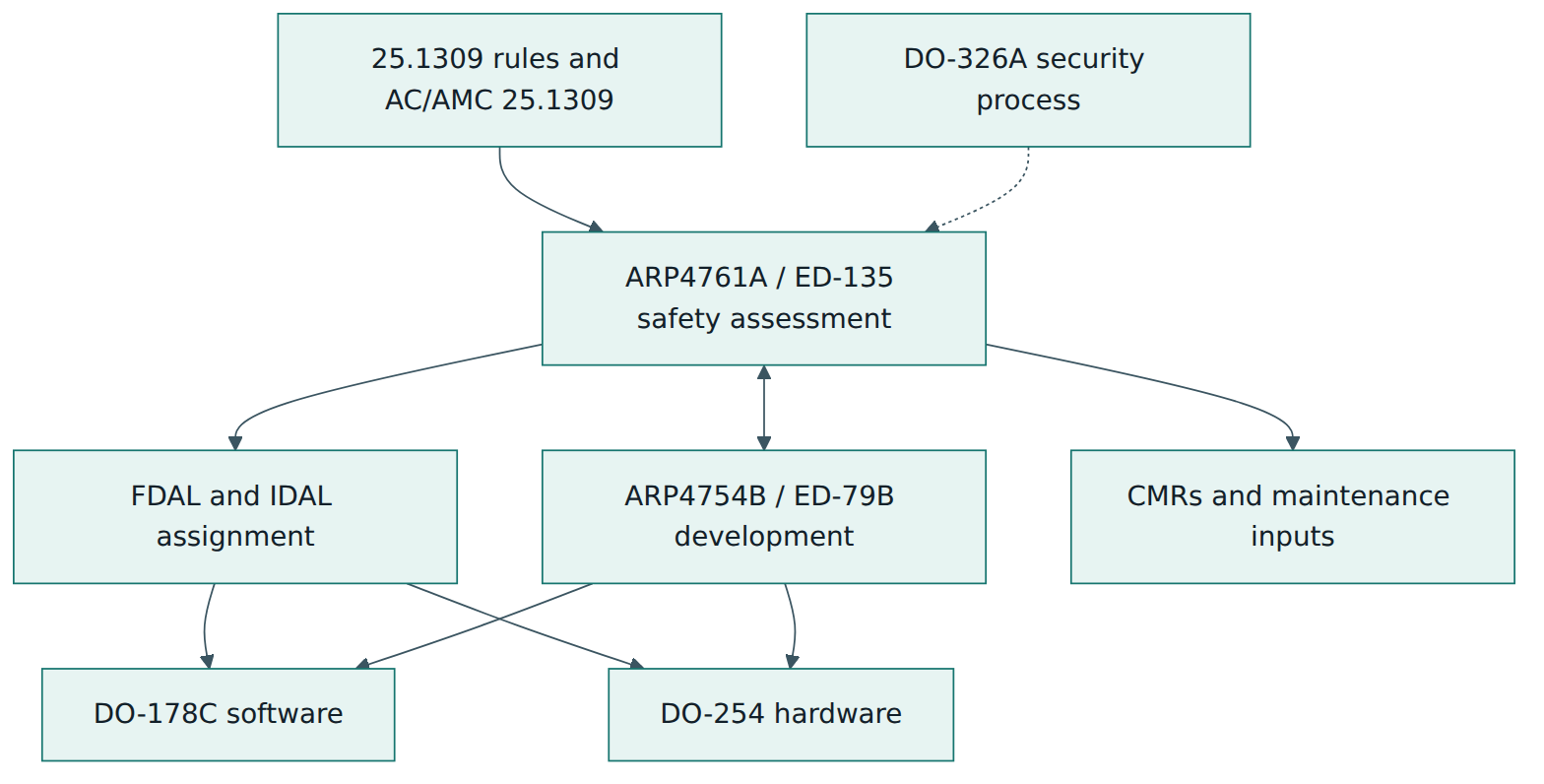
ARP4761A sits in a family of aerospace documents, each covering part of the picture. It also has cousins in other industries that use similar ideas with different vocabulary.
| Document | Focus | Relationship to ARP4761A |
|---|---|---|
| SAE ARP4754B / EUROCAE ED-79B | Development of civil aircraft and systems: requirements, validation, verification, configuration management, development assurance | Companion document, revised in the same month. Receives safety requirements and development assurance levels from the safety assessment and returns design data and verification evidence. |
| 14 CFR / CS 25.1309 with AC 25.1309-1B and AMC 25.1309 | The regulatory requirement and the authorities' advisory material for large aeroplanes | Sets the severity definitions and probability objectives that ARP4761A methods are used to meet. |
| RTCA DO-178C / EUROCAE ED-12C | Software development assurance | Takes the software level (IDAL) from the safety assessment; returns derived requirements that the safety team must assess. |
| RTCA DO-254 / EUROCAE ED-80 | Design assurance for complex airborne electronic hardware | Same role as DO-178C, for hardware items. |
| RTCA DO-326A / EUROCAE ED-202A | Airworthiness security process | Separate process for intentional threats; shares the failure condition view so that security effects can be judged against safety severity. |
| ISO 26262 | Functional safety of road vehicles | Similar ideas (hazard analysis, ASIL levels, FMEA, FTA, dependent failure analysis) but classifies risk by severity, exposure and controllability rather than by probability per flight hour. |
| IEC 61508 | Generic functional safety of electrical, electronic and programmable systems | Uses safety integrity levels and target failure measures; ARP4761A plays a comparable role for aircraft but with aviation-specific severity classes. |
| MIL-STD-882E | US Department of Defense system safety | A risk-matrix based system safety process for military programmes; military aircraft may use it alongside or instead of ARP4761-style methods. |
Key differences to keep in mind
Engineers moving from automotive often look for an equivalent to ISO 26262's controllability or exposure factors. In civil aviation, the crew's ability to cope is part of the severity classification itself, and the frequency is handled through probability per flight hour, not through a separate exposure rating. Engineers moving from IEC 61508 will find the idea of integrity levels familiar, but in aviation the development assurance level is assigned from the failure condition classification and the functional failure set, rather than from a risk reduction target.
Within aviation, the most important relationship is with ARP4754B. The two documents are designed as one process seen from two sides: development creates the design and its requirements, and safety assessment tells development what the design must achieve and checks that it does. A programme that treats them as separate teams with separate schedules usually discovers its safety problems late.
Common pitfalls and best practices
Common pitfalls
- Late hazard assessment – writing the FHA after the architecture is fixed turns it into paperwork and removes its main value, which is to shape the design.
- Assumed independence – multiplying probabilities of two channels without a common mode analysis, while they share software, power, routing or a maintenance procedure.
- Ignoring exposure time – treating every failure as instantly detected, which hides latent failures and makes numbers look far better than reality.
- Unvalidated crew assumptions – classifying a condition as Major because "the crew will notice and act" without checking alerts, workload and timing.
- Numbers without judgement – presenting a single probability as proof of safety while qualitative objectives, such as no single catastrophic failure, are not shown.
- Broken traceability – safety requirements from the PSSA that never reach the design or are never verified, so the SSA cannot close them.
- Copied analyses – reusing an FHA or FMEA from a previous aircraft without checking that the functions, environment and operations are the same.
Best practices
- Start at aircraft level – perform the AFHA and PASA early and keep them current, so that system work inherits consistent failure conditions.
- Make it a team sport – involve pilots, human factors, maintenance, installation and software specialists in hazard assessments and common cause analyses.
- Use one set of names – keep failure condition names and identifiers consistent across AFHA, SFHA, fault trees and the SSA so reviewers can trace them.
- Treat outputs as requirements – feed every safety requirement into the ARP4754B requirements process with an owner and a verification method.
- Combine methods – pair top-down fault trees with bottom-up FMEAs and with zonal, particular risk and common mode analyses to catch what each misses.
- Agree early with the authority – settle the revision, methods, failure rate sources and any novel arguments in the certification plan before analysis is far advanced.
- Keep models and analyses in sync – when using model-based tools, control versions so the analysis always matches the design baseline under review.
Summary and key takeaways
- ARP4761A (with its European twin ED-135, both December 2023) is the aerospace recommended practice for the safety assessment process of civil aircraft, systems and equipment.
- The process has six steps: AFHA, PASA, SFHA, PSSA, SSA and ASA, moving top-down to set requirements and bottom-up to show they are met.
- Methods are tools inside the process: FTA, dependence diagrams, Markov analysis, MBSA, FMEA/FMES, cascading effects analysis and the common cause analyses ZSA, PRA and CMA.
- Severity drives both the probability objective and the development assurance level; independence, proven by common mode analysis, is what allows levels to be shared.
- Random failures are analysed quantitatively; development errors are addressed through development assurance, never through a failure rate.
- Latent failures, exposure time and maintenance checks are central to realistic results.
- Following ARP4761A is an accepted way to show compliance, not a certificate; the authority reviews the assessment as part of aircraft or equipment approval.
- The safety assessment works hand in hand with ARP4754B and drives DO-178C and DO-254 levels.
Reflection questions
- Pick a function on an aircraft you know (for example cabin pressurisation). Which failure conditions would you list, and how would the flight phase change their severity?
- In your own organisation or industry, where do you rely on two things being independent? How would you prove that they really are?
- Why might a team be tempted to delay its hazard assessment, and what would you say to a project manager to bring it forward?
- Think of a backup system that is rarely used. How would you find out whether it still works, and how often would you check?
- If you were reviewing a supplier's fault tree that shows an excellent probability, which three questions would you ask first, and why?
Further reading and official sources
- ARP4761A – Guidelines for Conducting the Safety Assessment Process on Civil Aircraft, Systems, and Equipment – SAE International
- ED-135 – Guidelines for Conducting the Safety Assessment Process on Civil Airborne Systems and Equipment – EUROCAE
- ARP4754B – Guidelines for Development of Civil Aircraft and Systems – SAE International
- AC 25.1309-1B – System Design and Analysis – Federal Aviation Administration
- AC 20-174 – Development of Civil Aircraft and Systems – Federal Aviation Administration
- Easy Access Rules for Large Aeroplanes (CS-25, including AMC 25.1309) – European Union Aviation Safety Agency
- ARP4761 – Wikipedia
Original tutorial by xOps School (DevOpsSchool Private Limited), written from public sources about SAE ARP4761A. Not affiliated with or endorsed by the standard's owner; standard names are trademarks of their owners. Buy the official standard from its publisher for the authoritative text.